The radio clock control module is a control unit that is connected in the antenna line between the antenna amplifier and the radio. It demodulates and amplifies the radio time signal received by the rear window antenna, it checks the data, converts them and sends the time information via the K-bus to the instrument cluster for the purpose of correcting the clock.
Two hardware variants are used in order to adapt to the various radio time signal transmitters:
A clock is integrated in the instrument cluster that operates independent of the radio clock control module. The setting functions for date, hours and minutes as well as selection of 12 and 24 hour clock display are retained.
The clock in the instrument cluster is corrected with the radio time received by the radio clock control module. In addition, the changeover from summer time to winter time takes place automatically.
Adaptation to deviating time zones for Germany/Great Britain can still be carried out manually by correction of the displayed hour. Adaptation is retained even when a radio time signal is received.
The radio signal is continuously evaluated when terminal R is switched on. When the signal is intact, the time information is transferred to the instrument cluster approx. every 5 minutes.
With terminal R switched off, the radio time is transferred once a day.
If the clock in the instrument cluster is not set (e.g. after disconnecting the battery), the radio time (clock time and date) is adopted directly provided a valid time signal is available.
The minute display is corrected if the displayed time deviates within the range of +/-15 minutes from the radio time. The displayed hour value is not corrected.
If the displayed time deviates from the radio time by more than +/-15 minutes, a large deviation is assumed and the complete radio time (hours/minutes and date) is adopted.
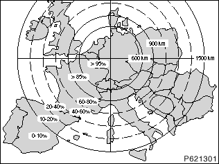
The radio clock signal is a longwave-based radio signal. Transmitters for radio times are available in Great Britain and Germany.
The following figures show the reception situation for both transmitters.
The following conditions apply:
Additional points to remember:
The figure above shows the reception conditions for the variant 1 (77.5 kHz)
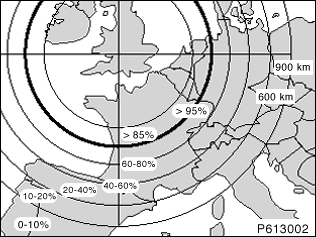
The figure above shows the reception conditions for the variant 2 (60 kHz)
Reception |
Field strength |
> 90 % |
> 10 |
85 % - 90 % |
9 |
75 % - 85 % |
8 |
60 % - 75 % |
7 |
50 % - 60 % |
6 |
10 % - 50 % |
5 |
The field strength can be read out via diagnosis.