Alternators
Alternators
Standard alternator
- To facilitate connection to the vehicle's electrical system, the standard alternator features two threaded pins at its rear for B+ (terminal 30) and D+ (terminal 61). The charge indicator lamp receives the terminal 61 signal via the exciter diodes.
Compact alternator with multifunction controller (MFR)
- The alternator with multifunction controller features only one threaded pin for the terminal connection B+ (terminal 30). The connection D+ (terminal 61 E) is located in the black 3-pin connector at the rear of the alternator. The terminal 15 connection is also located in this connector for voltage supply of the controller.
Compact alternator with multifunction controller (MFR) and start load response
- The alternator with multifunction controller (MFR) and start-load response does not differ externally from the alternator without the start-load response function. The difference only concerns the time limitation of the rated current during the start procedure.
Battery charge indicator lamp
The battery charge indicator lamp is activated in different ways depending on the type of controller.
- Standard regulator
- In the case of the standard controller, the battery charge indicator lamp is activated by the exciter diodes with the voltage generated by the stator winding and the controller. In the case of fault, the charge indicator lamp lights due to a voltage difference between terminal 15 (instrument cluster) and terminal 61.
- Multifunction controller:
- In the case of the multifunction controller, the battery charge indicator lamp is activated by means of an electronic switch integrated in the controller. This switch receives its voltage supply from terminal 15 on the 3-pin connector at the rear of the alternator. The controller measures internally the voltage difference between terminal 30 and terminal 15 and switches terminal 61 E to low in the case of a fault. The indicator lamp lights up.
Controller
The task of the controller is to set the rectified alternator voltage to a constant value irrespective of the alternator current and alternator speed.
- Multifunction controller:
The multi-function controller features an integrated fault detection facility. Indication is provided by the battery charge indicator lamp in the event of
- Failure of the belt drive ( Ualternator
= Uterminal 15
/ no phase signal)
- no charge due to a fault ( Ualternator
= Uterminal 15
)
- Interruption in excitation circuit
- Over-voltage due to a defective controller output stage ( Ualternator
> Uterminal 15
)
- Break in charge line ( Ualternator
- Uterminal 15
>= 3 V +/- 0.5 V )
- Multifunction controller with start load response
Fault detection is identical to that of the multifunction controller without start-load response
Start-load response function:
This function is intended to shorten the engine starting procedure
particularly at low ambient temperatures.
The task of the function is to eliminate a braking torque acting on the engine as the result of full excitation and current output. For this purpose, the load current is limited to 20 A during the initial phase. Following current limitation, the full power output is then slowly reached.
Comparison diagrams for oscillogram measuring system
Caution!
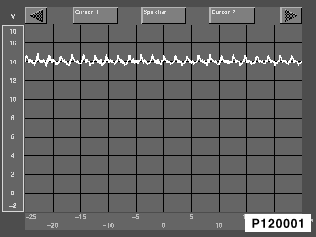
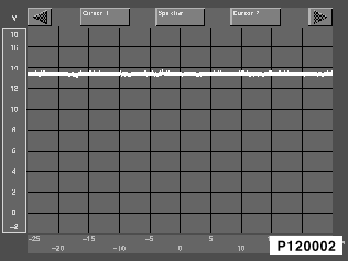
Comparison diagrams apply only to the standard alternator !!!
Oscillogram of a standard alternator in good working condition:
The display signal is located in the voltage range between 9 V and 16 V. The signal can differ considerably in appearance dependent on engine speed, load status and battery status.
Caution!
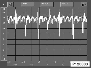
Comparison diagrams apply only to the standard alternator !!!
Oscillogram of a standard alternator with a defective diode:
The displayed signal is outside the voltage range between 9 V and 16 V at the voltage peaks and/or voltage dips. Depending on the type of fault, the voltage peaks can extend over the entire measuring range. This case indicates a break, short to ground or short to positive.


