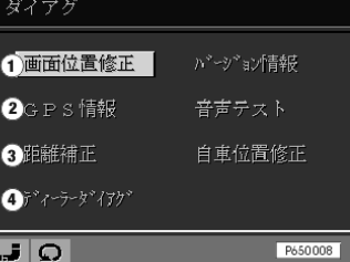
The sensor test can be selected as follows:
Fig. 1
1 |
Screen centre correction |
2 |
GPS information |
3 |
Tyre calibration |
4 |
VICS and GPS diagnosis |
Fig. 2
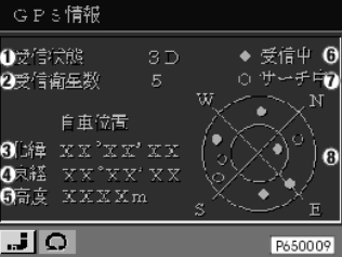
1 |
Detected position (0D,2D,3D) |
2 |
Number of satellites currently received by GPS |
3 |
Degree of longitude |
4 |
Degree of latitude |
5 |
Altitude |
6 |
Received satellites (explanation to 8) |
7 |
Satellites existing but not received (explanation to 8) |
8 |
Position and number of satellites |
Fig. 3
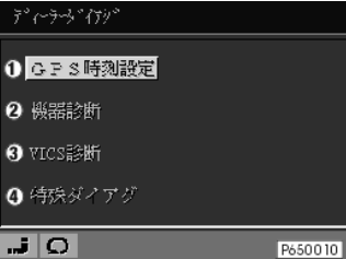
1 |
GPS time initialisation (transfers BC time to GPS receiver) |
2 |
NAC computer RAM-test, ROM-version |
3 |
VICS menu |
4 |
Special diagnosis (Fig. 5) |
Concerning 1: After replacing the GPS receiver, the initialization time can be shortened when the time is transferred from BC to GPS.
Fig. 4
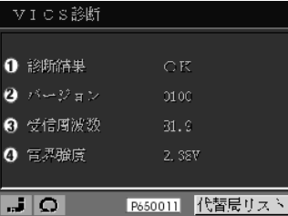
1 |
VICS status |
2 |
VICS version |
3 |
Frequency |
4 |
Receiving level |
Fig. 5
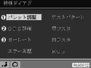
1 |
Colour range |
2 |
GPS data |
3 |
Gyro data (Fig. 6) |
Fig. 6
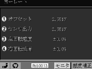
1 |
|
2 |
Gyro voltage |
3 |
Gyro correction value |
4 |
Gyro correction value |
Vehicle outside with clear upward view
Display Fig. 2 |
Setpoint |
If not OK: carry out the following test |
1 |
2D or 3D |
Test module GPS test |
2 |
>3 |
Test module GPS test |
3 |
Degree of longitude display |
Test module GPS test |
4 |
Degree of latitude display |
Test module GPS test |
5 |
Altitude display |
Test module GPS test |
6 |
|
|
7 |
|
|
8 |
>3 satellites |
Test module GPS test |
Drive several small diameter circles with the vehicle outdoors
Observe voltage change from gyro!
Display Fig. 6 |
Setpoint |
If not OK: carry out the following test |
1 |
|
|
2 |
When stationary and when driving straight ahead: 2500mV+/-500mV;while taking a corner: outside above-specified range. |
If value not OK: Replace navigation computer. |
3 |
|
|
4 |
|
|
Only with VICS receiver installed
Display Fig. 4 |
Setpoint |
If not OK: carry out the following test |
1 |
OK |
Test module, VICS receiver |
2 |
Version number |
|
3 |
Frequency |
Test module, VICS receiver |
4 |
Receiving level |
Test module, VICS receiver |
For 3 and 4: Display for VICS reception only (only in served area).