The high pressure pump in the common rail system delivers fuel under high pressure into the rail. During operation, the three pistons of the high pressure pump generate pressure peaks in the rail which can be made visible by means of measuring the rail pressure sensor signal with an oscilloscope. The shape of the signal makes it possible to determine the mechanical status of the high pressure pump.
In order to obtain a meaningful signal, rail pressure control must be active. The test module automatically switches from volumetric flow regulation to rail pressure control. As a result, two faults are stored in the DDE fault memory; these should be ignored and must be deleted once diagnosis has been completed.
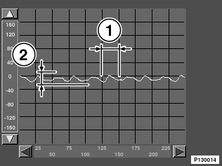
The figure below shows a rail pressure sensor signal that is in order thus indicating an intact high pressure pump. The signal pulsating uniformly at a period of approx. 25 ms and an amplitude of approx. 20 mV can be clearly seen.
The maximum permissible value for the amplitude is 40 mV.

Fig. 1: OK signal
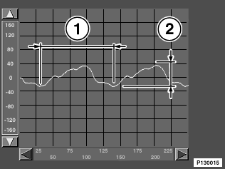
In contrast to this, the next figure shows a signal that has been generated by a defective high pressure pump (one piston of the pump failed).
The following factors characterise the difference compared to Fig. 1:

Fig. 2: not OK signal