Water pump
The housing is made of die cast aluminium or plastic and is screw-mounted on the timing case cover. The dual temperature sensor for the coolant is installed in the water pump housing. This dual temperature sensor is located at the point where the coolant flows out of the engine.
Radiator
An engine oil cooler is additionally fitted for specific country variants.
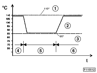
The control of the engine cooling system with a conventional thermostat is determined by the coolant temperature only. This control system can be subdivided into three operating ranges:
With the aid of the characteristic map thermostat, the coolant temperature can now be influenced specifically within the thermostat control range.
As a result the engine can be operated at a higher coolant temperature in the partial load range. This achieves more efficient combustion thus reducing fuel consumption and pollutant emissions.
On the other hand, lower coolant temperatures are intentionally set under full load operating conditions. As a result the tendency to knocking is reduced and the engine can be operated close to optimum ignition timing.
|
Control characteristics of characteristic map cooling |
|---|---|
1 |
Characteristic curve of a 110 o C thermostat |
2 |
Characteristic curve of a characteristic map thermostat |
3 |
Characteristic curve of an 85 o C thermostat |
4 |
Partial load range |
5 |
Full load range |
6 |
Partial load range |
With the aid of the characteristic map thermostat, the coolant temperature is specifically increased in the partial load range. This characteristic map thermostat is controlled by the engine control unit dependent on a characteristic map.
This characteristic map is determined by the following factors:
Design of the characteristic map thermostat
The characteristic map thermostat is an integral thermostat, i.e. the thermostat and thermostat cover make up one unit.
The principle mechanical design of the characteristic map thermostat corresponds to that of a conventional thermostat. However, a heating element is additionally integrated in the expansion element (wax element).
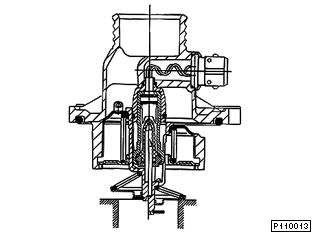
Cross sectional view of the characteristic map thermostat |
|
The housing cover of the characteristic map thermostat is made of an aluminium pressure die casting. The electrical connection for the heating element integrated in the thermocouple of the characteristic map thermostat is integrated in the thermostat cover.
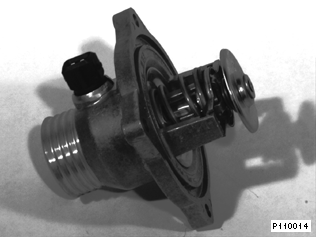
Characteristic map thermostat with electrical connection for heating element |
|
Function of the characteristic map thermostat
The characteristic map thermostat is tuned such that it opens at a coolant temperature at the thermostat of 103oC from the engine inlet without intervention of the integrated heating facility. Due to the coolant being heated in the engine, the temperature at the engine outlet (place of installation for the coolant temperature sensor for DME and instrument cluster display) is approx. 110o C at this point in operation. On reaching this engine operating temperature the characteristic map thermostat begins to open without control intervention.
In the event of control intervention by the DME control unit, power (12 V) is applied to the heating element integrated in the thermostat. Heating the expansion element means that the thermostat opens at lower coolant temperatures (thermostat control range: approx. 80oC - 103oC).
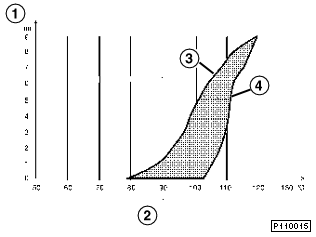
1 |
Opening path of the thermostat |
2 |
Coolant temperature |
3 |
Activation of heating element with 12 V |
4 |
Activation of heating element with 0 V |
If the coolant temperature exceeds 113oC at the engine outlet, the heating of the characteristic map thermostat is activated by the DME irrespective of the other parameters.
Diagnosis
The line connection and the function of the characteristic map thermostat are monitored by the diagnosis function in the DME control unit. Any faults are stored in the fault code memory of the DME control unit.
Coolant temperature gauge
The characteristics of the coolant temperature gauge in the instrument cluster are adapted to the higher temperature level required for the characteristic map thermostat.
The pointer of the coolant temperature gauge in the instrument cluster is located in the mid-position at coolant temperatures of
75oC - 113o C
in centre position.