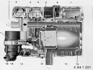
Components of the independent park heater/auxiliary heater
Observe the following points if the independent park heater/auxiliary heater Thermo Top Z is installed:
Replacement devices are supplied with analog line activation and must be coded for the K bus according to the table below.
Model series/engine variant |
Independent park heater/auxiliary heater without K-bus |
Independent park heater/auxiliary heater with K-bus |
E46 / Diesel (M47) |
as from series launch up to production break PU98 (1998_09) |
as from production break PU98 (1998_09) |
E38 / Diesel (M51, M57) |
from production break PU98 (1998_09) to March 99 (1999_03) |
as from March 99 (1999_03) |
E39 / Diesel (M51, M57) |
from production break PU98 (1998_09) to March 99 (1999_03) |
as from March 99 (1999_03) |
E38, E39 / petrol engine |
|
as from March 99 (1999_03) |
E53 |
|
All models |
Operation |
analog with lines |
digital via K-bus |
Diagnosis |
Not possible |
With fault code memory queries |
.

The heater plug and flame monitor have been combined to form one component, the heater plug/flame monitor (4). This can not be replaced separately.
The combustion air blower (2) is an integral part of the combustion chamber (11) and cannot be replaced individually. The CO setting is conducted ex factory in this independent park heater/auxiliary heater and can subsequently no longer be varied.
The circulation pump (14) is mounted externally on the heater and can be replaced separately when conduction repairs .
The metering pump is mounted on the underbody and can be replaced separately when conducting repairs.
The combustion chamber (11) together with control unit (7) (with integrated coolant temperature sensor ) control and diagnose the independent park heater/auxiliary heater. The complete independent park heater/auxiliary heater unit should be replaced in case of repair (defective control unit or defective temperature sensor).
The activation of the independent park heater/auxiliary heater via K bus is available in the function test instructions in the next test step.
On activation, the glow plug, circulating pump and combustion-air fan are started up. After 30 seconds, the fuel metering pump is activated and the combustion-air fan is switched off for 30 seconds. The combustion-air fan is then brought up to practically full load in one ramp and within approx. 60 seconds. When the full load fuel supply has been reached in this period, the glow plug is switched off and the combustion-air fan is turned up to full load. During the next 45 seconds and also during normal combustion, the glow plug takes on the task of flame monitor and check the flame formation. The automatically controlled heating operation then begins. If there is no flame formation or a break in the flame, a start repetition is automatically initiated. If there is again no flame formation, the fuel supply is discontinued and there is a fault shutdown with overrun of the combustion-air fan.
On activation, the glow plug, circulating pump and combustion-air fan are started up. After 30 seconds, the fuel metering pump is activated and the combustion-air fan is switched off for 30 seconds. The combustion-air fan is then brought up to practically full load in two ramps and within approx. 60 seconds. After a stabilisation phase (constant engine speed) of 15 seconds, the combustion-air fan is again brought up to practically full load on a ramp of approx. 50 seconds. When the full load fuel supply has been reached in this period, the glow plug is switched off and the combustion-air fan is turned up to full load. During the next 45 seconds and also during normal combustion, the glow plug takes on the task of flame monitor and check the flame formation. The automatically controlled heating operation then begins. If there is again no flame formation or a break in the flame, the fuel supply is discontinued and there is a fault shutdown with overrun of the combustion-air fan. If there is a break in the flame during normal combustion, a restart is automatically initiated.
After the temperature has risen to approx. 72°C, the heating unit switches to energy-saving part-load operation. If the temperature of the coolant continues to rise to approx. 76°C, the heating unit switches to the control pause. This also takes place when the duration of the total combustion exceeds approx. 76 minutes. The circulating pump, the car's own heater blower and the operating indicator remain in operation during the control pause. When the coolant temperature drops to approx. 71°C, the heating unit again switches to part load. If the temperature rises to approx. 76°C, the heating unit switches again to the control pause. If the temperature of the coolant falls due to increased heat requirements during part-load operation, the heating unit switches back to full-load operation at approx. 56°C.
The heating operation sequence is the same on the diesel heating unit. However, if the temperature of the coolant during the control pause does not drop below approx. 71°C within 900 seconds, the heating unit starts with the next distinction of the coolant temperature of approx. 71°C with the regular starting process in full load operation.
Combustion is stopped and the overrun begins. However, the circulating pump and the combustion-air fan continue to run to cool down the heating unit (overrun) and are switched off automatically.