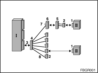
The BYTEFLIGHT bus system has a star-shaped structure. The individual satellites (= control units with/without sensors) are interconnected across a star coupler by means of fibre-optic cables. The star coupler in the BYTEFLIGHT bus system is the Safety and Gateway Module. There is a transmission and a reception module (transmitter and receiver) as a unit in each satellite for connecting to the BYTEFLIGHT bus. The unit has an integrated transmit and receive diode. The optical testing and programming unit can be used to test the transmitter and receiver of a control unit.
Fig. 1 shows the various plug-in connections of the safety system. The Safety and Gateway Module has a six-pin socket for plugging the six-pin fibre-optic cable connector. The connection between the Safety and Gateway Module and the satellites is by means of fibre-optic cable. In the case of the door satellites (or door modules), there is an additional isolation point between the door and frame of the vehicle. The satellites are supplied by the Safety and Gateway Module with a voltage between 9 V and 11 V. However, the connector for the power supply is not shown in Fig. 1.

Fig. 1: Overview of the plug-in connections of the safety system
I: Safety and Gateway Module |
II: Satellite |
1: Socket for satellite |
2: Connector for satellite |
3: Socket for Safety and Gateway Module |
4: Connector for Safety and Gateway Module |
5: Socket for door |
6: Connector for door |
7: Power supply from Safety and Gateway Module to satellite |
8: Fibre-optic cable |
If no communication is possible with the Safety and Gateway Module , this can be caused by the following:
If the power supply from the Safety and Gateway Module is defective, no communication with the and other control unit is possible. In this case, the cause of the fault must always be searched for first at the Safety and Gateway Module.
If no communication is possible with a certain satellite, this can be caused by the following:
Prior to each optical test, the power supply of the control units suspected of being defective must be checked. The satellites are supplied by the Safety and Gateway Module with a voltage between 9 V and 11 V. The optical testing and programming unit can then be used to pinpoint the error cause on the control unit or the fibre-optic cable. The test programs for the optical test on the BYTEFLIGHT bus can be found under function selection: Body, Bus Functions, BYTEFLIGHT Functions and Optical Test.
The optical testing and programming unit
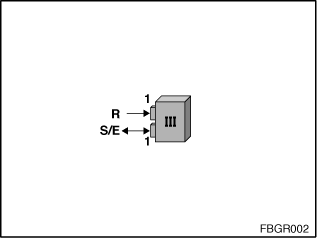
Fig. 2: Optical testing and programming unit (III)
III: Optical testing and programming unit |
1: Socket for plugging the satellite connector |
R: Reference receiver (indicated on the optical testing and programming unit by a single arrow) |
S/E: Transmitter-receiver diode (indicated on the optical testing and programming unit by a double arrow) |
The optical testing and programming unit (BYTEFLIGHT section) has a socket for adaptation of the satellite connector. The transmitter-receiver diode for the optical test is integrated here. Another socket is necessary for calibration of the optical testing and programming unit (BYTEFLIGHT section). A reference receiver for calibration is integrated here.
For the optical test of a control unit (or fibre-optic cable), the control unit (or fibre-optic cable) must be connected to the optical testing and programming unit using an adapter. However, each adapter has a different attenuation value. So that these different attenuation values are taken into account in the optical test, calibration must be carried out before each optical test. During the calibration, there is also a check as to whether the adapter is OK. The various calibrations, depending on whether the Safety and Gateway Module, a satellite or a fibre-optic cable is being tested, are shown below.
1. The optical testing and programming unit has two sockets for fitting a satellite connector. For the test of the Safety and Gateway Module (or fibre-optic cable using the satellite), the SIM adapter (or SIM wiring harness adapter) is required. However, these adapters cannot be connected directly to the optical testing and programming unit. Therefore, for calibration, the six-pin SIM adapter (A3 = 663133) must be connected to the SIM wiring harness adapter (A4 = 663134) . The satellite connectors (2) must be connected to the optical testing and programming unit.
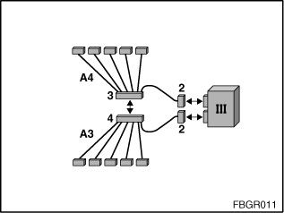
Fig. 3: Calibration for the test of the Safety and Gateway Module and fibre-optic cable using the satellite
2. To test the satellite, the satellite adapter (A1 = 663131) is required. For calibration, the two satellite connectors (2) are connected to the optical testing and programming unit.
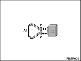
Fig. 4: Calibration for testing satellites
3. The optical testing and programming unit has two sockets for fitting a satellite connector. For the test of the fibre-optic cable, an adapter with a socket is required. However, the socket cannot be connected directly to the optical testing and programming unit. Therefore, for calibration, the satellite wiring harness adapter (A2 = 663132) must be connected with the satellite adapter (A1 = 663131). The satellite connectors (2) must be connected to the optical testing and programming unit.
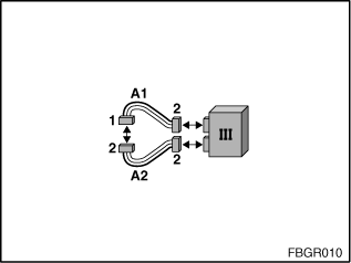
Fig. 5: Calibration for the test of the fibre-optic cable using the Safety and Gateway Module
For the optical test of a control unit (or fibre-optic cable), the control unit (or fibre-optic cable) must be connected to the optical testing and programming unit using an adapter. The different adapters required to test the Safety and Gateway Module, satellites or fibre-optic cable are shown below.
1. To test the fibre-optic cable (I), the six-pin SIM adapter (A3 = 663133) is required.
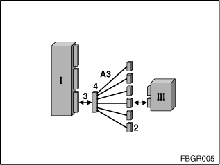
Fig. 6: Test of Safety and Gateway Module
2. To test the fibre-optic cable using the satellite (II), the six-pin SIM wiring harness adapter (A4 = 663134) is required.
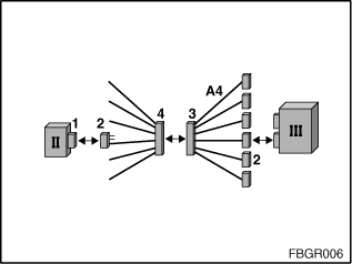
Fig. 7: Test of fibre-optic cable using the satellite
3. To test the satellite (II), the satellite adapter (A1 = 663131) is required. The satellite adapter (A1) has, alongside the fibre-optic cable, two more electrical wires. The two wires are needed for the power supply of the satellite. The voltage is generated by the optical testing and programming unit (III).
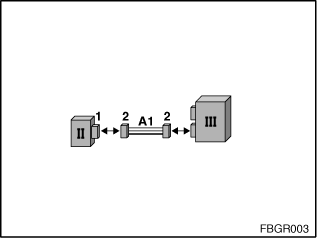
Fig. 8: Test of satellite
4. For the test of the fibre-optic cable using the Safety and Gateway Module (I), you required the satellites wiring harness adapter (A2 = 663132) .
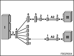
Fig. 9: Testing the fibre-optic cable using the Safety and Gateway Module
All work on the airbags must be carried out with the battery disconnected!
Only connect and disconnect BYTEFLIGHT control units with the fuse removed from the Safety and Gateway Module!
If a fibre-optic cable on the BYTEFLIGHT bus has to be repaired, it must be borne in mind that there may only be one join in a fibre-optic cable. If there is already a join due to a door connector, the fibre-optic cable must not be repaired. In the case of a defect, the fibre-optic cable must be replaced!