Note! Structure of this document.
The most important diagnosis instructions are described at the start of this document. These are followed by the functional description.
If problems occur on deleting the fault code memory following a repair, use the following procedure:
Important!
In some cases, indicator and warning lamps for certain faults only go out after a short test drive.
After replacing the DSC unit or DSC control unit The parameters for the Run Flat Indicator (RPA) as well as the cruise-control system must be coded using Progman.
With regard to the DSC function, the DSC control unit codes itself. In this operation, the vehicle identification number is also stored. This means that adjustment of the steering-angle sensor with DSC 8/DSC 8Plus is not required. For every startup (ignition on), the DSC compares the stored vehicle identification number with the current vehicle identification number. DSC codes itself according to the type of vehicle if the vehicle identification numbers do not match. This opportunity is used to reset the learned adjustment values of the sensors to the base setting (exception: longitudinal acceleration sensor).
Perform the following operations:
After replacement of the DSC sensor, the service function ”Adjustment DSC sensor” must be run. The longitudinal acceleration sensor is calibrated in the DSC sensor.
The steering-angle sensor forms a unit with the steering column switching centre. The steering-angle sensor cannot be replaced on its own. The service function ”Calibration steering-angle sensor” or in the case of vehicles with active steering the service function ”Commissioning/Adjustment active steering” must be run after the following work:
As series standard, the E70 is equipped with dynamic stability control (DSC).
E60/E61 as of 03/2007.
The DSC is an enhancement of DSC 8Plus. To make a distinction, this chassis control system is called ”DSC Premium”. System supplier for the DSC is Bosch.
The control functions of the DSC have been optimised. The improvement was achieved by installing a return-flow pump with 6 pistons as well as more powerful electronics. In comparison with the previous model (E53), the E70 has been given extended functions:
Further road safety results from the combination with other systems:
DSC is a driving dynamics system that maintains driving stability. DSC optimises:
The DSC also detects unstable driving states such as understeer or oversteer. DSC helps to maintain the vehicle on a safe course within the physical boundaries.
To do so, the DSC must be aware of the following dynamic measurement variables:
In addition, the driver request is detected from the steering angle and the brake pressure the driver applies to the pedal. Furthermore, wheel-speed sensors deliver information on the speed of the individual wheels. The available measured values are used to determine the actual status in which the vehicle is moving at the moment. The actual condition is compared with target values calculated in the DSC control unit. If the current actual values deviate from the target state, DSC becomes active and actively intervenes in the brake system or in the engine management system, as the case may be.
The following components for dynamic stability control are described:
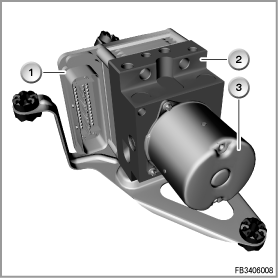
The DSC unit consists of the DSC control unit and a hydraulic unit. The DSC control unit activates the hydraulic unit via valve coils.

Index |
Explanation |
Index |
Explanation |
|---|---|---|---|
1 |
DSC control unit with plug-in connection |
2 |
Hydraulic unit |
3 |
Pump motor |
|
|
The DSC unit contains a brake pressure sensor. This brake pressure sensor picks up the braking pressure applied via the brake pedal and the brake booster.
The brake pressure sensor has a measuring range of 0 to 250 bar. Its zero point is only synchronised while the vehicle is being driven.
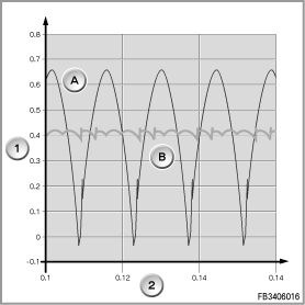
The new concept of the DSC unit enables more exact control. 2 x 3 pump elements with 6.5 mm work in the pump motor. This concept results in significantly improved pressure dynamics. It means that the brake pedal pulses to lesser degree during ABS control. It also leads to higher control quality with Hill Descent Control (HDC).
Index |
Explanation |
Index |
Explanation |
|---|---|---|---|
A |
DSC 8Plus |
B |
DSC Premium |
1 |
Volumetric flow [l/min] |
2 |
Time [s] |
The distribution box at the junction box electronics (JBE) supplies the DSC unit with voltage. Once terminal 30 for the return-flow pump, once terminal 30 for the solenoid valves. The DSC control unit receives terminal 30g.
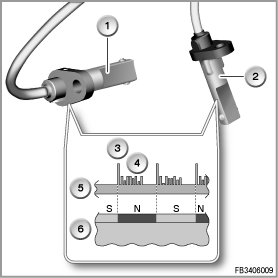
The active wheel-speed sensors determine the circumferential wheel speed of the individual wheels. In addition, the wheel-speed sensors detect the direction of rotation (forwards or backwards). When a wheel is at a standstill, the wheel-speed sensor transmits an impulse every
0.75 seconds. The current impulse indicates the availability of the wheel-speed sensor.
The following advantages result from active wheel-speed sensors:
Index |
Explanation |
Index |
Explanation |
|---|---|---|---|
1 |
Wheel-speed sensor, front axle |
2 |
Wheel-speed sensor, rear axle |
3 |
Impulse for the engine speed |
4 |
Additional information such as direction of rotation and air gap |
5 |
Signal path |
6 |
Wheel bearing with magnets |
On the front and rear axles, there is a circle of magnets (increment wheel) around the wheel bearing. The north and south poles of the increment wheel alternate. A north pole with a south pole corresponds to 1 increment (comparable with tooth/gap of an increment gear). The wheel-speed sensor consists of 3 Hall sensors and an electronic evaluation unit.
The active wheel-speed sensors change their electrical resistance under the influence of a magnetic field. Each increment causes 2 impulses in the wheel-speed sensor (96 impulses / rotation of wheel). For data transfer to the control unit, additional data is appended to the edge of the impulse. Functionally, this integrated data processing goes beyond pure engine speed detection. The following additional information is possible, e.g.:
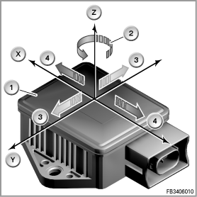
The DSC sensor measures:
Index |
Explanation |
Index |
Explanation |
|---|---|---|---|
1 |
DSC sensor |
2 |
Plug-in connection |
The sensor element consists of 2 piezo-electric acceleration sensors. A mass is suspended on a spring in the measurement cell of the acceleration sensor.
With an accelerates motion, 2 masses suspended on springs are also accelerated. The force necessary for this creates a mechanical voltage in the piezoelectrical material. The shift in electrical charge this creates is picked up with electrodes made of metal and processed as an electrical signal. The yaw rate is derived from the difference between the two acceleration signals. The DSC sensor thus delivers a yaw rate and an acceleration signal.
The longitudinal acceleration sensor is required for the drive-off assistant.
The DSC sensor is connected via the chassis CAN (F-CAN) with the DSC control unit.
The DDE control unit supplies the DSC sensor with voltage.
The steering-angle sensor is installed in the steering column switch cluster (SZL). The steering-angle sensor measures the steering-wheel angle optically and without contact. The steering-angle sensor is fitted on the board with the electronic evaluation unit. The steering-angle sensor consists of the following components: code disk and optical sensor.
The code disk is connected to the steering wheel via the buffer spring cassette. When the steering wheel is moved, the code disk moves within the optical sensor. There are various line patterns for evaluation on the code disk.
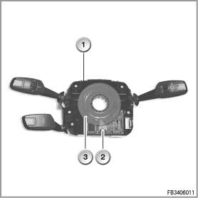
Index |
Explanation |
Index |
Explanation |
|---|---|---|---|
1 |
Steering column switch cluster (SZL) |
2 |
Optical sensor |
3 |
Code disk |
|
|
The SZL is connected via the chassis CAN (F-CAN) with the DSC control unit.
The DTC button is used to change the operating mode of the chassis control system. The DTC button bears the lettering ”DTC”. The DTC button can be used to select 3 switching states:
E70:
the DTC button is in the centre console switching centre (no control unit). The centre console switching centre is connected to the integrated heater / automatic climate control (IHKA). The IHKA sends the signal on the K-CAN.
E60 and E61 as of 03/2007:
the DTC button is in the switch block to the left of the ashtray. The switch block is connected to the centre console switch centre (SZM). The SZM control unit is installed in the carrier behind the glove compartment.
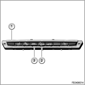
The graphic shows the E70
Index |
Explanation |
Index |
Explanation |
|---|---|---|---|
1 |
Centre console switch centre |
2 |
HDC button HDC means Hill Descent Control: hill descent assistance |
3 |
DTC button |
|
|
E70:
the HDC button is also in the centre console switching centre.
E60 and E61:
the hill descent control (HDC) can be assigned to the freely programmable buttons on the steering wheel. The HDC can also be activated via iDrive.
The DSC receives additional input signals from the following components:
A low brake fluid level is picked up (in the expansion tank via a reed contact) and notified to the DSC control unit. With a low brake fluid level, DSC is disabled. Otherwise, there is a danger that air will be drawn into the brake system.
Together with the signal from the brake pressure sensor (only with DSC), braking operations are detected.
The brake-light switch contains 2 switches (2-stage). A signal is then made available to the DSC across a line. The engine control unit receives both signals. The engine control unit sends the signal on the PT-CAN. The DSC control unit uses both signals to detect whether the brake pedal has been pressed.
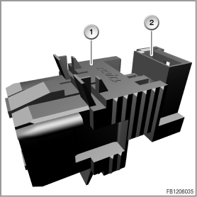
Index |
Explanation |
Index |
Explanation |
|---|---|---|---|
1 |
Brake-light switch |
2 |
Plug-in connection |
The Car Access System (CAS) supplies the brake-light switch with terminal R.
The brake pad wear sensors (front left and rear right in the internal brake pads) provide additional information on the thickness of the brake pad. This additional information (2 reference points) is used to synchronise the calculated value of the DSC.
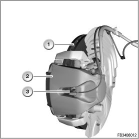
Index |
Explanation |
Index |
Explanation |
|---|---|---|---|
1 |
Brake disc |
2 |
Brake caliper |
3 |
Brake pad wear sensor (example, rear axle) |
|
|
A critical brake lining thickness is indicated in the instrument cluster by a service requirement display (Condition Based Service CBS) as well as the general brake warning light in red.
The following additional control units are involved in the dynamic stability control:
In the event of failure malfunction of the DSC, a Check Control symbol appears in the LC display. The Check Control symbols all have a certain meaning.
If there is a Check Control message, additional supplementary instructions can be displayed on the Central Information Display (CID).
The CAS receives a processed speed signal from the DSC. The CAS recognises from the signal whether the vehicle is stationary or moving.
The distribution box at the junction box electronics supplies the DSC unit with voltage.
Terminal 30 for the return-flow pump as well as the solenoid valve.
Terminal 30g for the DSC control unit.
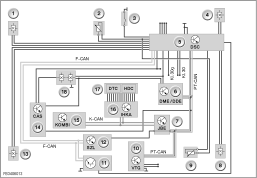
The graphic shows the E70
Index |
Explanation |
Index |
Explanation |
|---|---|---|---|
1 |
Wheel-speed sensor, front left |
2 |
Brake pad wear sensor, front left |
3 |
Brake-fluid level switch |
4 |
Wheel-speed sensor, front right |
5 |
DSC (Dynamic Stability Control) |
6 |
Digital Engine Electronics or Digital Diesel Electronics (DME or DDE) |
7 |
Junction box electronics (JBE) |
8 |
Wheel-speed sensor, rear right |
9 |
Brake pad wear sensor, front left |
10 |
Transfer box (VTG) |
11 |
DSC sensor |
12 |
Steering column switch cluster (SZL) |
13 |
Wheel-speed sensor, rear left |
14 |
Car Access System (CAS) |
15 |
Instrument cluster (KOMBI) |
16 |
Integrated automatic heating and air conditioning system (IHKA) |
17 |
Centre console switch centre |
18 |
Brake-light switch |
F-CAN |
Chassis CAN |
K CAN |
Body CAN |
Terminal 30 |
Terminal 30 |
Terminal 30g |
Terminal 30g |
PT-CAN |
Powertrain CAN |
|
|
The following new system functions for den E70 are described for the DSC:
Other known system functions for the DSC are:
The following additional functions that do not belong to driving dynamics control are integrated:
DTC is an optimised version of DSC for certain road conditions on forward momentum. The dynamic traction control (DTC) provides improved traction with partially reduced driving stability and is thus only recommended for exceptional situations. In the following exceptional situations, it can be useful to activate DTC briefly:
The function DTC corresponds to that of DSC with a slightly modified control strategy. DTC can be activated by shutting down DSC (DTC button). By means of brake intervention, DTC replicates the function of a conventional differential interlock. It increases the input torque to wheels on a road surface with a higher coefficient of friction.
Advantage: with DTC, greater traction is available. Interventions to stabilise the vehicle (e.g. reduction in the engine output) are carried out slightly later than in the case of DSC. In certain situations, the driver must intervene correctively to stabilise the vehicle.
Application of the brake pads at an early stage shortens the response time of the brakes. With rapid closure of the throttle (angle of the accelerator pedal), the brake pads are applied immediately. The DSC creates a low brake pressure without perceptibly decelerating the vehicle. This compensates for the clearance between the brake pad and brake disc. If there is no braking within half a second, the created early brake pressure is taken back. Applying the brake pads at an early stage is active at a driving speed greater than 70 kph.
Dry braking removes the moisture deposited on the brake disc when driving on wet roads or in the rain. Here, the brake pads are applied slightly. This function also shortens the response time of the brakes. Depending on the signal of the rain sensor or the position of the wiper switch, the DSC creates low brake pressure in cycles. This does not lead to any perceptible braking on the vehicle. The brake pads are applied in cycles. The brake discs are wiped regularly in the process. How often and for how long the brake pads are applied depends on:
Fading means: the braking action diminishes due to high brake-disc temperature. As a reaction to detected fading, DSC increases the brake pressure beyond the brake pressure applied by the driver. At very high brake-disc temperature, the fading compensation leads to the following being displayed:
The DSC detects fading as follows: The DSC compares the current vehicle deceleration with a target value related to the current brake pressure. The DSC increases the brake pressure until the target deceleration is reached or until all the wheels are subject to ABS control. The operation is terminated when the brake pedal is no longer pressed or a speed threshold is undershot.
When driving off on an incline, a switch from the brake pedal to the accelerator pedal is required. Here, the drive-off assistant prevents the vehicle from rolling in the following situations:
Here, the brake pressure required to hold the vehicle is maintained. The road surface inclination is picked up by the longitudinal acceleration sensor in the DSC control unit. The necessary braking torque or engine torque is calculated from the road surface inclination. After detection of the wish to drive off, the brake pressure is reduced as soon as the applied engine torque is sufficient to move the vehicle in the desired direction of travel. If the parking brake is actuated, the drive-off assistant is disabled. If there is no wish to drive off within approx. 2 seconds after releasing the brake pedal, the drive-off assistant is also disabled.
The cruise control with braking function is functionally integrated in the DSC. The cruise control keeps the selected speed constant between 30 kph and 250 kph.
In comparison with the conventional cruise control, there are the following additional functions:
The EMF is a parking brake.
With the engine running, the DSC applies the retaining force hydraulically.
With the engine off, the EMF applies the retaining force mechanically via the actuating unit.
The anti-lock braking system (ABS) prevents the wheels from blocking on braking. Advantage: short braking distance, the direction of the vehicle remains stable and the vehicle can be steered. The brake pressure on all wheels is regulated in such a way that each wheel runs in an optimised slip range. Here, the slip is regulated in such a way that the highest possible braking and cornering forces can be transferred.
The electronic braking force distribution (EBV) is a component of the ABS. EBV regulates the braking force distribution between the front and rear axles depending on the load. Advantage: independently of the load, optimised braking distances with simultaneous high driving stability are achieved. The brake lining wear is better distributed. If the ABS fails, the EBV function remains as long as possible. The EBV function requires the signals from at least 2 wheel-speed sensors per axle.
The Cornering Brake Control (CBC) is an expansion of the ABS. CBC increases driving stability on braking in curves (”curve logic”). Advantage: optimization of the driving stability with partial braking on cornering. The shift in wheel loads on cornering (even with light braking) can reduce driving stability. If required, CBC creates a stabilising counter-torque outside of the ABS feedback control range during light braking.
The engine drag-torque control (MSR) prevents the blocking tendency of the drive wheels on smooth roadways. On downshifting or in the case of abrupt load changes (especially on a roadway with a low coefficient of friction), there is a danger that the drive wheels block due to the engine drag-torque. Via the wheel-speed sensors, MSR detects the blocking tendency even as it is about to happen. MSR briefly reduces the engine drag-torque by accelerating slightly. Advantage: the drive wheels retain their cornering forces even in the coasting (overrun) mode.
The Automatic Stability Control (ASC) uses brake and engine interventions to prevent the wheels from spinning on accelerating. Advantage: more traction and better driving stability. If the wheels on the driven axle have different levels of adhesion, the wheel with the tendency to slip is braked. If necessary, the engine output is also reduced.
The current drive status of the vehicle is detected by the dynamic stability control (DSC) by evaluation of the sensor signal. This drive status is compared with the target values determined using a calculation model. This enable detection of unstable driving states even as they are about to happen. In the case of deviations that are above a control threshold stored in the DSC control unit, the vehicle is stabilised. The stabilisation (within physical boundaries) is achieved by reducing the engine output and individual braking of wheels. DSC intervention override the functions ABS and ASC. The DSC function can be deactivated using a button. The R56 has no dynamic traction control (DTC).
The Dynamic Braking Control (DBC) provides support in emergency braking situations by automatically boosting the brake pressure. Advantage: the shortest possible braking distances in emergency braking situations by reaching the ABS feedback control range on all 4 wheels. In emergency braking situations, it is frequently the case that the brake pedal is not pressed strongly enough. This means that the ABS feedback control range is not reached. The return-flow pump brings the braking into the ABS feedback control range by increasing the brake pressure in the following situations:
The dynamic stability control (DSC) specifies the target value for 4-wheel drive control with xDrive. The DSC control unit calculates the locking moment for the multi-plate clutch in the transfer box. The target value depends on the tendency of the vehicle to oversteer or understeer and the wheelslip. The target value is sent on the PT-CAN to the VTG control unit. The VTG control unit returns the actually set locking moment to the DSC control unit. The DSC control unit calculates the locking moment of the multi-plate clutch as follows:
Hill Descent Control (HDC) is an automatic cruise control for hill descents with 4-wheel-drive vehicles. The HDC can be switched on and off at the centre console switch centre. HDC automatically reduces the driving speed. The driving speed is reduced to slightly more than walking speed by means of brake intervention on all four wheels. This results in a stable hill descent on a steep and smooth / icy road surface. The HDC keeps this speed constant (the DSC functions all remain active). The accelerator pedal and brake pedal or the steering-column lever for cruise control can be used to vary the driving speed steplessly within specified values. Ex works, the lower freely programmable button on the multifunction steering wheel is set for the HDC.
The trailer stabilisation control detects seesaw motion of a trailer around the vertical axis. The system works as of a speed of approx. 65 kph with the electrical connector for trailer occupied. The dynamic stability control (DSC) monitors the yawing motion of the vehicle with the help of the DSC sensors. If the limit value is exceeded on the swinging trailer, the engine output is reduced. The DSC also automatically brakes all 4 wheels. With disabled or defective DSC, the trailer stabilisation control is also disabled.
The Run Flat Indicator (RPA) is not a function of the driving dynamics control. The RPA is integrated in the DSC control unit, as for this function the 4 wheel-speed signals are required. The system uses the 4 wheel speeds to compare deviations in the rolling circumferences of the individual wheels. This means that a creeping loss of tyre inflation pressure is detected.
The Run Flat Indicator can be initialised as follows:
CBS is not a function of the driving dynamics control. Condition Based Service means ”requirement-oriented service”. Various maintenance items are integrated in the CBS, e.g. engine oil, spark plugs and brake pads. The remaining distances for the front and rear brake pads are calculated separately in the DSC control unit. The state of the brake pad wear sensors is also used for the calculation (reference point at 6 mm and 4 mm).
Important! Replacing the DSC control unit.
On replacement of the DSC control unit, the repair instructions must be observed (special tool necessary).
The following service functions are available in the BMW diagnosis system:
After replacement, the DSC control unit must be coded.
After every engine start, the DSC is operational.
No liability can be accepted for printing or other errors. Subject to changes of a technical nature