The setting of the ACC or long range sensor (LRR = Long Range Radar) is required if:
The sensor setting must be made on a special setting bay with guide rails firmly fixed to the floor.
The sensor may only be set using the special tools and test equipment approved by BMW.
All test equipment must be in a satisfactory condition and must show no signs of damage.
Attention should be paid to ensuring that the guide rail and the neighbouring area are free of dirt and other objects.
The function of the ACC system depends greatly on the exact setting of the sensor. This is why the adjustment must be made with the utmost care in line with the instructions in the test module.
Pay attention to the following points:
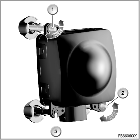
The ACC / LRR sensor is set by means of two adjusting screws.

Sensor ACC2
1: Adjusting screw, top left, for vertical adjustment
2: Adjusting screw, bottom right, for horizontal adjustment
3: Fixed mount
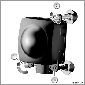
LRR Long Range Radar
1: Adjusting screw, bottom left, for horizontal adjustment
2: Adjusting screw, top right, for vertical adjustment
3: Fixed mount
During the adjustment of the sensor, the direction and angle of rotation are specified in the test module. These values apply only to a narrow range (linear range) close to the correct setting value. If the specified values in the test module mean that no rapid approximation (approx. 7 correction loops) of the target value is possible, the sensor is located outside the linear range. In these cases, remove the sensor and make a rough setting of the sensor.
Note: the setting values for the rough setting are shown in the help document for the service function in the chapter ”Used radar sensors”.
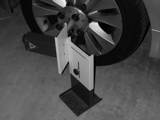
Setting the slit diaphragm
Place the slit diaphragm and housing of the laser pointer exactly vertical. Set the height of the slit diaphragm in such a way that the light of the laser pointer passes exactly through the slit diaphragm.
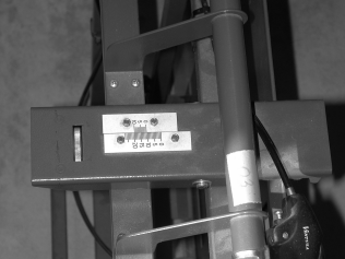
Vertical mirror adjustment
Scale and knurled wheel for the vertical mirror adjustment.
Horizontal mirror adjustment
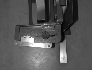
Scale and retaining screw for the horizontal mirror adjustment.
Folding device for mirror
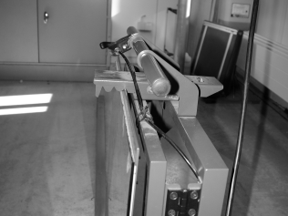
Folding device to fold the mirror forwards and back. The illustration shows the mirror in the ”rear” position (mirror folded away from vehicle).