The new generation of 6-cylinder petrol engines (NG6) is being continued with an enhancement.
With the new turbocharged 6-cylinder petrol engine N54 with direct fuel injection, BMW is once again entering the arena of turbo technology.
Direct fuel injection of the 2nd generation (DI2) is used on the new turbocharged engine. The direct fuel injection (HPI: High Precision Injection) delivers additional levels of autonomy in measuring the amount of fuel and fuel injection period (multiple fuel injection, depending on the load and engine speed up to 3 times) as well as in the mixture distribution in the combustion chamber. This enables a positive influence on the power output, engine torque, consumption and pollutant emissions.
The mixture cooling by the directly injected fuel means the compression can be increased compared to a turbocharged engine with intake pipe fuel injection. This improves efficiency.
The use of direct fuel injection creates a homogeneous mixture formation in the entire combustion chamber. Homogeneous mixture formation means that the fuel-air ratio is regulated stoichiometrically in the same way as for intake pipe fuel injection (Lambda = 1).
(”Stoichiometrically” refers to a fuel-air ratio of 14.8 kilograms of air to 1 kilogram of fuel.) The homogeneous mixture formation means that a conventional system for exhaust re-treatment can be deployed.
The bi-turbo concept in particular ensure significantly more spontaneous power output development. Instead of a large exhaust turbocharger, two smaller units each supply three cylinders with compressed air. The major advantage of the smaller exhaust turbochargers is their low mass moment of inertia. Even the smallest actuation of the accelerator pedal module leads to an immediate pressure build-up in response.
At the same time, the use of variable timing (double VANOS) enables optimised turbocharge changes, which leads to high engine torque at low engine speed, ensuring superior elasticity.
The following components of the N54 engine are described:
There are 3 sensors on the board in the DME control unit (MSD80):
The temperature sensor is used for the thermal calculation of the components in the DME control unit.
The ambient-pressure sensor is required for calculation of the mixture composition. The ambient pressure falls with increasing altitude above sea level.
The voltage sensor monitors the power supply via terminal 87.
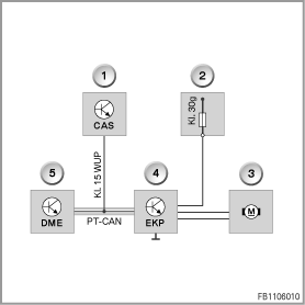
The digital engine electronics control unit determines the fuel requirement of the engine. The required volume of fuel is sent as a message via the PT-CAN to the EKP (electric fuel pump) control unit. This message is converted by the EKP control unit into an output voltage. This output voltage is used to regulate the speed of the electrical fuel pump, thus achieving supply for the high-pressure pump that is in line with requirements.

Index |
Explanation |
Index |
Explanation |
|---|---|---|---|
1 |
Car Access System (CAS) |
2 |
Distribution box in the junction box |
3 |
Electrical fuel pump |
4 |
Electric fuel pump control unit |
5 |
DME control unit |
|
|
Terminal. 15 WUP |
Wake-up line (terminal 15 wake up) |
Terminal. 30g |
Terminal 30 switched |
PT-CAN |
Powertrain CAN |
|
|
The electric fuel pump is an in-tank pump.
As of terminal 15 On, the electric fuel pump is switched on.
The high-pressure fuel pump compresses the fuel (range of 50 to 200 bar) and feeds it to the rail.
The high-pressure fuel pump is bolted onto the rear end of the vacuum pump. The drive shaft of the high-pressure fuel pump is connected to the drive shaft of the evacuating pump.
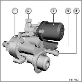
Index |
Explanation |
Index |
Explanation |
|---|---|---|---|
1 |
High-pressure fuel pump |
2 |
Connection for the high pressure line to the rail |
3 |
Volume control valve |
4 |
Electrical connection |
5 |
Connection for the low pressure line from the fuel pump |
|
|
The volume control valve controls the fuel delivery pressure in the rail. The volume control valve is activated via a pulse-modulated signal (PWM signal) from the DME control unit.Depending on the PWM signal, various throttle cross-sections are released and the necessary fuel supply volume for each engine load is set. In addition, there is the possibility to reduce the pressure in the rail.
If a fault in the system is diagnosed, e.g. failure of the high-pressure sensor, the current to the volume control valve is cut off. The fuel then reaches the rail via a so-called bypass valve.
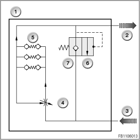
Index |
Explanation |
Index |
Explanation |
|---|---|---|---|
1 |
High-pressure fuel pump |
2 |
Connection for the high pressure line to the rail |
3 |
Connection for the low pressure line from the fuel pump |
4 |
Volume control valve |
5 |
3 Pistons as well as intake and exhaust valves |
6 |
Pressure relief valve |
7 |
Bypass valve |
|
|
The volume control valve is a component of the high-pressure pump and can be removed during service.
In the rail, the compressed fuel is stored temporarily and distributed to the injectors.
The rail-pressure sensor measures the current fuel delivery pressure in the rail.
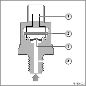
Index |
Explanation |
Index |
Explanation |
|---|---|---|---|
1 |
Electrical connection |
2 |
Evaluating circuit |
3 |
Membrane with sensor element |
4 |
High-pressure connection |
The fuel delivery pressure passes through the high-pressure connection to the membrane with sensor element. The deformation of the membrane is converted via the sensor element into an electrical signal. The evaluating circuit processes the signal and forwards an analog voltage signal to the DME. The voltage signal rises in linear form with increasing fuel delivery pressure.
The signal from the rail-pressure sensor is an important input signal of the DME for activation of the volume control valve (component of the high-pressure pump).
If the rail-pressure sensor fails, the volume control valve is activated in emergency operation by the DME.
The injector sprays the fuel into the combustion chamber under high pressure. The injector opens the tip of the nozzle needle outwards and forms a ring gap that is only a few micrometres wide. The ring gap shapes the beamed direct fuel injection and ensures even, cone-shaped divergence.
The piezo-electric activation has the following advantages compared to activation via solenoid coils:
This results in significant improvements with regard to pollutant emission as well as fuel consumption.
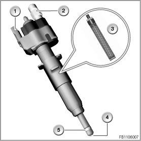
Index |
Explanation |
Index |
Explanation |
|---|---|---|---|
1 |
Electrical connection |
2 |
Fuel pipe connection |
3 |
Layers of piezo elements |
4 |
Nozzle needle, tip opens outwards |
5 |
Teflon ring |
|
|
A piezo element is an electromechanical converter. The piezo element is a type of ceramic that converts electrical energy directly into mechanical energy (power/travel). The piezo element expands when voltage is applied. This generates the lift of the nozzle needle.
To achieve a greater lift, a piezo element can be structured in a number of layers.
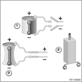
Index |
Explanation |
Index |
Explanation |
|---|---|---|---|
1 |
Piezo element without voltage |
2 |
Layers of piezo elements |
3 |
Piezo element, voltage applied |
|
|
The intake-manifold pressure sensor measures the partial vacuum in the intake system. The intake-manifold partial vacuum serves as a substitute value for the load signal. The intake-manifold pressure sensor is fitted behind the throttle valve.
The engine is equipped with 2 exhaust turbochargers (one exhaust turbocharger at the exhaust manifold for cylinders 1 to 3, one exhaust turbocharger at the exhaust manifold for cylinders 4 to 6). The turbines permit especially high exhaust-gas temperatures (1050 °C technology), leading to a noticeable reduction in fuel consumption particularly at high load.
The boost pressure of the exhaust turbocharger is controlled by the DME by means of a bypass valve (wastegate valve). A portion of the exhaust gases is fed via the bypass valve to the turbine.
The bypass valves are activated via electropneumatic pressure transducers by the DME and their setting can be varied.
There are two connections on the bearing housing for the engine cooling circuit and two connections for the oil circuit for cooling and lubrication of the exhaust turbocharger.
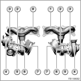
Index |
Explanation |
Index |
Explanation |
|---|---|---|---|
1 |
Dual-panel exhaust manifold (cylinders 1 to 3), welded to turbine housing |
2 |
Oil supply |
3 |
Coolant outlet |
4 |
Diaphragm can of the bypass valve |
5 |
Oil return |
6 |
Coolant inlet |
7 |
Exhaust turbocharger with bypass valve |
8 |
Dual-panel exhaust manifold (cylinders 4 to 6), welded to turbine housing |
The engine has a volume-flow-regulated oil pump. This pump supplied exactly the amount of oil necessary to reach the control pressure level. The oil pump is driven by a chain from the crankshaft.
An electric motor drives the coolant pump. The power output of the electric motor (400 Watts) is controlled by a control electronics circuit. This control electronics circuit is connected via the bit-serial data interface with the DME (Digital Engine Electronics). The DME uses the load, operating range and the data of the temperature sensors to determine the required cooling output. The DME sends to the corresponding signals for control of the coolant pump to control electronics circuit.
The motor of the coolant pump is flooded with coolant. This cools the motor and the control electronics circuit. The coolant also lubricates the bearings of the electric coolant pump.
The oil condition sensor measures the following variables:
The oil condition sensor sends the measured values to the DME.
The variable camshaft timing control serves to enhance the torque in the lower and middle engine speed range.
One VANOS solenoid valve each on the intake side and exhaust side control a VANOS adjustment unit. The VANOS solenoid valves are activated by the digital engine electronics control unit.
The timing of the engine can be influenced using the two variable VANOS adjustment units.
A greater valve overlap results in lower amounts of residual gas at idle speed. Nitrous oxide components are reduced by internal exhaust-gas recirculation in the partial load range.
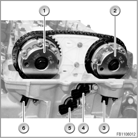
Index |
Explanation |
Index |
Explanation |
|---|---|---|---|
1 |
VANOS adjustment unit, exhaust side |
2 |
VANOS adjustment unit, inlet side |
3 |
Intake camshaft sensor |
4 |
Solenoid valve |
5 |
Solenoid valve |
6 |
Exhaust camshaft sensor |
Caution! Do not confuse the VANOS adjustment units.
The VANOS adjustment units for the inlet and exhaust camshafts have different adjusting paths. If the VANOS adjustment units are confused, bottoming valves can lead to engine damage.
The installation side is engraved on the front of the VANOS adjustment unit.
A split crankcase made of aluminium is used on the engine. To increase the rigidity, the lower part is designed as a bed-plate construction.
The following system functions are described:
The boost pressure of the exhaust turbocharger is controlled by the DME by means of a bypass valve (wastegate valve). The bypass valves are activated via the electropneumatic pressure transducer by the DME (map-controlled).
In addition to the bypass valves, 2 blow off valves are fitted. Without the blow off valve, the exhaust turbocharger would have to work against the backpressure of the closed throttle valve and become slower.
When the throttle valve closes, the blow off valves open due to the increased partial vacuum in the intake pipe. When opened, the blow off valves connect the inlet side of the compressor with the exhaust side of the compressor. This prevents excessive backpressure.
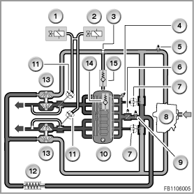
Index |
Explanation |
Index |
Explanation |
|---|---|---|---|
1 |
Electropneumatic pressure converter (for adjusting the bypass valve on the exhaust turbocharger for cylinders 4 to 6), activated by the DME |
2 |
Electropneumatic pressure converter (for adjusting the bypass valve on the exhaust turbocharger for cylinders 1 to 3), activated by the DME |
3 |
Engine ventilation heating |
4 |
Intake-manifold pressure sensor |
5 |
Intake air temperature sensor |
6 |
Electric Throttle Valve Actuator |
7 |
Blow off valves, controlled via the intake pipe partial vacuum |
8 |
Intake muffler |
9 |
Charge-air pressure sensor |
10 |
Engine |
11 |
Bypass valves (wastegate valves) |
12 |
Intercooler |
13 |
Exhaust turbocharger |
14 |
Non-return valve with pressure limitation |
15 |
Non-return valve to the fresh air pipe |
|
|
The engine ventilation is pressure-controlled. Depending on the intake pipe partial vacuum and boost pressure, venting takes place either via a 6-way distributor rail in the inlet ports or into the fresh air pipe before the exhaust turbocharger (cylinders 4 to 6). The distributor rail is integrated in the cylinder head cover.
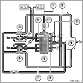
Index |
Explanation |
Index |
Explanation |
|---|---|---|---|
1 |
Engine ventilation heating |
2 |
Fresh air pipe before the exhaust turbocharger (cylinders 4 to 6) |
3 |
Electric Throttle Valve Actuator |
4 |
Intake muffler |
5 |
Air collector for intake air |
6 |
Engine |
7 |
Fresh air pipe before the exhaust turbocharger (cylinders 1 to 3) |
8 |
Exhaust turbocharger |
9 |
Non-return valve with pressure limitation |
10 |
Non-return valve to the fresh air pipe |
Two valves are fitted for engine ventilation.
For the cooling system with electric coolant pump, the possibilities of the conventional cooling system are exploited. The heat management determines the current cooling requirement and regulates the cooling system accordingly.
The following components are influenced by heat management:
The cooling output of the system is adapted by means of a freely variable volumetric flow of the coolant.
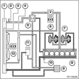
Index |
Explanation |
Index |
Explanation |
|---|---|---|---|
1 |
Radiator |
2 |
Coolant-temperature sensor at the radiator outlet |
3 |
Gearbox oil cooler |
4 |
Gearbox oil cooler with thermostat |
5 |
Characteristic map thermostat |
6 |
Electric coolant pump |
7 |
Exhaust turbocharger |
8 |
Engine |
9 |
Heat exchanger for heating system |
10 |
Coolant-temperature sensor on engine |
11 |
Expansion tank for coolant |
12 |
Electric Fan |
The heat management determines the current cooling requirement and regulates the cooling system accordingly. Under certain circumstances, the coolant pump can even be switched off completely, for example to accelerate heating of the coolant in the warm-up phase.
When the engine is at a standstill and is very hot, the coolant pump also pumps. The cooling output can be requested independent of the engine speed.
The heat management now means that, over and above the map thermostat, various characteristic maps can be used for control of the coolant pump. In this way, the engine control unit can adapt the engine temperature to the driving characteristics.
The engine control unit (MSD80) regulates the following temperature ranges:
Engine oil thermostat
The engine oil thermostat is located at the oil filter.
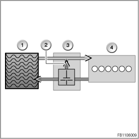
Index |
Explanation |
Index |
Explanation |
|---|---|---|---|
1 |
Engine oil cooler |
2 |
Short circuit |
3 |
Engine oil thermostat |
4 |
Engine |
The engine oil thermostat is opened or closed on a temperature-dependent basis. However, it never closes completely; it has a minimum flow through to the engine oil cooler.
Up to an engine oil temperature of 110 °C, the engine oil thermostat is closed.
The supplied engine oil is returned to the return flow via the engine oil thermostat in the short circuit. This ensures faster warming up of the engine.
As of an engine oil temperature of 110 °C, the engine oil thermostat opens and reduces the aperture in the short circuit. This increases the oil flow rate in the line to the engine oil cooler. As of approx. 125 °C, the thermostat is fully opened.
The volume-flow-regulated oil pump (pendulum slide cell pump) supplies exactly the amount of oil necessary to reach the control pressure level.
The oil pressure that is applied across the control line on a control piston with oblique thrust surface (hinged bracket) counteracts the force of a compression spring.
If the oil requirement of the engine rises, the pressure in the lubricating system falls and thus also at the control piston. The oil pump raises the delivery volume and sets up the previous pressure conditions. When the oil requirement of the engine falls, the pump regulates a lower delivery volume according to the position of the control piston.
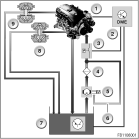
Index |
Explanation |
Index |
Explanation |
|---|---|---|---|
1 |
Engine |
2 |
Digital Engine Electronics (DME) |
3 |
Oil-pressure switch |
4 |
Oil filter |
5 |
Volume-flow-regulated oil pump with control pistons |
6 |
Control line (oil pressure) |
7 |
Oil condition sensor in the oil sump |
8 |
Exhaust turbocharger |
9 |
Exhaust turbocharger |
|
|
The oil condition sensor indicates the engine oil temperature and oil level to the DME control unit. To calculate the oil level, the DME control unit calculates the time it takes to heat up and cool down the engine oil. The oil pressure switch indicates the oil pressure. The DME control unit activates the warning and indicator lamp in the instrument cluster via the PT-CAN (red: oil pressure low; yellow: oil level low)
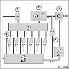
Index |
Explanation |
Index |
Explanation |
|---|---|---|---|
1 |
Rail pressure sensor |
2 |
High-pressure pump with volume control valve |
3 |
Electrical fuel pump |
4 |
Fuel low pressure sensor |
5 |
Fuel injectors |
6 |
Rail |
EKP |
Electric fuel pump control unit |
DME |
Digital Engine Electronics |
PT-CAN |
Powertrain CAN |
|
|
According to system pressure applied between the fuel pump and high-pressure pump, the fuel low pressure sensor sends a voltage signal to the engine control unit (DME control unit).
The system pressure (fuel low pressure) is determined with the fuel low pressure sensor before the high-pressure pump.
The DME control unit runs a continuous comparison between the specified pressure and actual pressure. If there is a deviation between the specified pressure and actual pressure, the DME control unit increases or decreases the voltage for the electric fuel pump, sent as a message across the PT-CAN to the EKP control unit. The EKP control unit converts the message into an output voltage for the electric fuel pump. These regulates the required delivery pressure for the engine (or high-pressure pump).
In the event of a signal failure (fuel low pressure sensor), with terminal 15 On the electric fuel pump is operated with pre-control.
If the CAN bus fails, the electric fuel pump is operated via the EKP control unit with the prevailing on-board supply voltage.
The high-pressure pump compresses the fuel to a pressure between 50 and 200 bar.
The compressed fuel reaches the rail via the high pressure line. In the rail, the compressed fuel is stored temporarily and distributed to the injectors.
The rail-pressure sensor measures the current fuel delivery pressure in the rail. When the volume control valve in the high-pressure pump opens, the excess fuel delivered is returned to the inlet.
If the high-pressure pump fails, restricted driving is possible.
If the temperature of the coolant or of the engine oil becomes excessive during engine operation, certain functions in the vehicle are influenced in such a way that the engine cooling has more energy available.
The measures are divided into 2 operating modes:
Warning! Only work on the fuel system when the engine is cold.
At coolant temperatures above 40 °C, fuel can emerge at high speed when the injectors are loosened.
No liability can be accepted for printing or other errors. Subject to changes of a technical nature