Active seat E65, E66
Active seat E65, E66
The active seat serves to relax the back muscles and spinal column.
As of 09/2006, a pneumatic system will be deployed. The pneumatic system replaces the hydraulic system used to date.
Brief description of components
The following components are described:
- SMFA and SMBF: driver seat module and passenger seat module
- BZM: Centre console switch centre
- CAS: Car Access System
- Button for active seat
- Lumbar support active seat drive
- Pressure distributor
- Air cushion
- Lumbar support
- SMFA and SMBF: driver seat module and passenger seat module
The seat module controls the lumbar support active seat drive and the pressure distributor. The driver's seat and front passenger's seat each have a lumbar support active seat drive and a pressure distributor. The seat module switches the function indicator lamp of the button for the active seat (one LED each in the left-hand switch block and right-hand switch block at the centre console switch centre). The seat module is connected on the K-CAN P (body CAN PERIPHERALS).
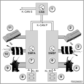
Index
|
Explanation
|
Index
|
Explanation
|
1
|
Car Access System (CAS)
|
2
|
Pressure distributor for passenger active seat
|
3
|
Lumbar support for passenger active seat drive
|
4
|
Valve block for lumbar-support adjustment, passenger
|
5
|
Rear distribution box
|
6
|
Passenger seat module (SMBF)
|
7
|
Driver seat module (SMFA)
|
8
|
Front distribution box
|
9
|
Valve block for lumbar-support adjustment, driver
|
10
|
Lumbar support active seat drive, driver
|
11
|
Pressure distributor for driver active seat
|
|
|
K-CAN P
|
Body CAN PERIPHERALS
|
K-CAN S
|
Body CAN SYSTEM
|
Terminal 30
|
Terminal 30
|
|
|
- BZM: Centre console switch centre
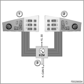
The BZM accommodates the controller as well as the switch blocks with the buttons for seat adjustment. The button signals for the driver seat adjustment and passenger seat adjustment are processed in the BZM.
The BZM transforms the button signal for the active seat (on/off) as well as the button signals for the lumbar-support adjustment into a digital signal. The BZM sends the signal as a message on the K-CAN S (body CAN SYSTEM).
Index
|
Explanation
|
Index
|
Explanation
|
1
|
Left-hand switch block on the centre console switch centre
|
2
|
Right-hand switch block on the centre console switch centre
|
3
|
Control panel module, centre console (BZM)
|
|
|
K-CAN S
|
Body CAN SYSTEM
|
Terminal 30
|
Terminal 30
|
- CAS: Car Access System
CAS contains the gateway function between K-CAN S and K-CAN P (K-CAN S stands for body CAN SYSTEM; K-CAN P stands for body CAN PERIPHERALS).
The CAS receives the CAN message from the BZM on the K-CAN S. The CAS forwards the CAN message across the K-CAN P to the corresponding seat module.
- Button for active seat as well as button for lumbar-support adjustment
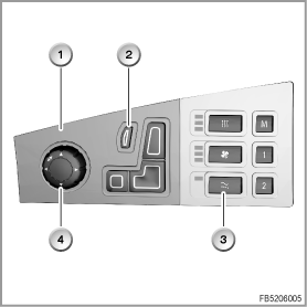
A button for the active seat as well as a button for the lumbar-support adjustment are fitted in each switch block on the centre console switch centre.
The button signals are sent across a ribbon cable to the centre console switch centre (BZM).
Index
|
Explanation
|
Index
|
Explanation
|
1
|
Left-hand switch block on the centre console switch centre
|
2
|
Button for lumbar-support adjustment
|
3
|
Button for active seat
|
4
|
Control button
|
- Lumbar support active seat drive
The lumbar support active seat drive contains the following components:
- Pneumatic pump with pump motor
The pneumatic pump supplies the air cushions in the active seat and the lumbar cushions with compressed air.
The pneumatic pump is driven by a DC motor.
- Solenoid valve
The solenoid valve forwards the air flow from the pneumatic pump as follows:
- to the lumbar cushions
or
- to the pressure distributor for the air cushions of the active seat
- Pressure relief valve
The pressure relief valve protects the system against excessive system pressure. The pressure relief valve is fitted after the pneumatic pump in the supply line.
- Control electronics
The control electronics have the following functions:
- Activation of the pump motor
The control electronics control 2 output stages at the pump motor.
Active seat function selected:
the pump motor runs with reduced power output.
Lumbar support function selected:
the pump motor runs with full power output.
The control electronics only activate the pump motor to inflate the 4 air cushions and the lumbar cushions.
- Activation of the solenoid valve
According to the selected function (active seat or lumbar support), the control electronics switch the solenoid valve. The air flow is directed to the downstream components.
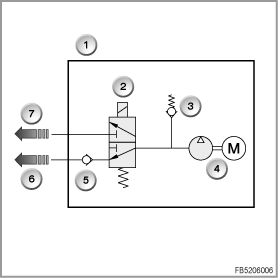
Index
|
Explanation
|
Index
|
Explanation
|
1
|
Lumbar support active seat drive, driver or passenger
|
2
|
Solenoid valve
|
3
|
Pressure relief valve
|
4
|
Pneumatic pump with pump motor
|
5
|
Non-return valve
|
6
|
to the pressure distributor in the active seat
|
7
|
to the lumbar cushions
|
|
|
- Pressure distributor
The pressure distributor distributes the air flow generated by the pneumatic pump to the 4 air cushions. The pressure distributor automatically regulates the inflation and deflation of the air cushions.
The pressure distributor consists of the following components:
- Drive unit
The drive mechanism consists of the drive motor and gearing. If the active seat function is activated, the drive motor permanently drives the unit for pressure distribution.
- Micro-switch for switching the pump motor on and off
The switch probes a signal disk with 4 cams in the drive mechanism (4 cams for the inflation and deflation of the individual air cushions). This picks up the work cycle. One revolution of the drive mechanism is a work cycle and it lasts approx. 80 seconds.
To deflate the air cushions, only the pump motor of the pneumatic pump is switched off. The drive unit in the pressure distributor continues to run.
The micro-switch is directly connected to the seat module.
- Unit for pressure distribution
The unit for pressure distribution distributes the air flow to the 4 air cushions.
A camshaft activates slide valves that enable inflation, pressure-holding and deflation of the air cushions.
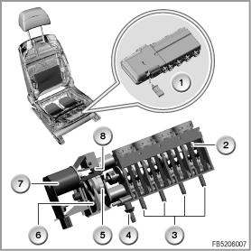
Index
|
Explanation
|
Index
|
Explanation
|
1
|
Pressure distributor
|
2
|
Camshaft
|
3
|
Compressed air connection (to the air cushions)
|
4
|
Compressed air connection (from lumbar support active seat drive)
|
5
|
Signal disk
|
6
|
Gearing
|
7
|
Drive motor
|
8
|
Micro-switch
|
- Air cushions
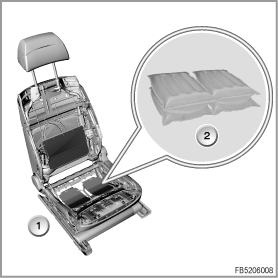
Four air cushions are fitted in the active seat. Two air cushions are arranged one above the other on the left-hand and right-hand seat cushions.
Index
|
Explanation
|
Index
|
Explanation
|
1
|
Air cushions in the active seat
|
2
|
Air cushion
|
- Lumbar support
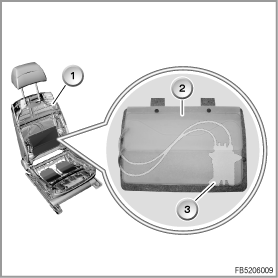
The lumbar support in the backrest consists of 2 inflatable lumbar cushions with a total of 2 valves in one valve block. The valve technology used is not based on a solenoid valve rather on a wire made of shape memory alloy. As of a certain temperature, this wire changes its grid structure and contracts. The wire always attempts to reassume its original shape.
For each lumbar cushion, there is a valve with 2 wires, one for opening the deflation duct and one for opening the inflation duct. Without current, the valves are closed.
The pneumatic pump supplies the lumbar cushion with compressed air. Depending on the selected setting, the individual air cushions are filled or emptied. This means that the lumbar support can vary its height and strength (adjustment of upper lumbar support and adjustment of lower lumbar support).
Index
|
Explanation
|
Index
|
Explanation
|
1
|
Lumbar cushion in the active seat
|
2
|
Lumbar cushion
|
3
|
Valve block (on the back)
|
|
|
System functions
The following system functions are described:
- After-run
- Standardisation after disconnecting the battery
- Deactivation with undervoltage and overvoltage
- Cutoff with high lateral acceleration
- After-run
If the system is switched off via the active seat button, the 4 air cushions must be deflated.
Deflation: With the pump motor switched off, the pressure distributor completes a full work cycle.
- Standardisation after disconnecting the battery
If the active system is not fully deflated after disconnecting the battery or resetting the seat module, activation takes place. The signal is sent by the micro-switch in the pressure distributor. With the pump motor switched off, the pressure distributor completes a full work cycle.
- Deactivation with undervoltage and overvoltage
The driver seat module (SMFA) or passenger seat module (SMBF) detect undervoltage and overvoltage. The seat module switches off the drive for the active seat.
Undervoltage: on-board supply voltage less than 9 Volts
Overvoltage: on-board supply voltage greater than 16 Volts
- Cutoff with high lateral acceleration
If the driving speed and lateral acceleration are above a defined value for approx. 0.25 seconds, the active seat function for the driver's seat is disabled. The function display (an LED) remains switched on. If the value is again undershot for approx. 3 seconds, the system resumes the function at the stopped position.
The DSC control unit calculates the driving speed and lateral acceleration. The DSC control unit sends the signals as a message on the PT-CAN.
Notes:
Option 455 ”Active seat for driver and passenger” is only delivered together with optional extra 488 ”Lumbar support for driver and passenger”.
Country-specific versions
USA, Canada
On account of the seat occupation mat, it is not possible to equip the front passenger's seat with an active seat.


