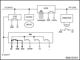
The terminal control is distributed across various control units. The following block diagram provides an overview of the control units involved and the integration in the vehicle electrical system.

PM |
Power module |
CAS |
Car Access System |
CD-GW |
Control Display (Gateway) |
SGM |
Safety and Gateway Module |
DME/DDE |
Digital Engine Electronics /Diesel Electronics |
|
|
K-CAN S |
Bus system for body functions, System |
K-CAN P |
Bus system body functions, Peripherals |
MOST |
Bus system in the area of audio and communication |
byteflight |
Bus system for airbag control units |
PT-CAN |
Bus system for power train and chassis functions |
There are the following terminals:
Terminal 30U and terminal 30B:
The battery cable is divided into a line to the power module (PM) and one to the safety battery terminal (SBK) for power supply in the engine compartment. Terminal 30U and terminal 30B run out of the power module (PM). These two terminals are normally always energised and only opened in the event of a short-circuit or other fault (corresponds to battery isolation). Almost all control units are supplied across these two terminals (2 thick cables leading away from the PM).
Not supplied across terminal 30U or terminal 30B are:
Consumer units supplied via the fuse box in the engine compartment (e.g. VTC engines, SLP, common rail, electric fan)
Control units and consumer units supplied directly from the power module (e.g. PDC, DME, CAS, LM, RLS, FBD receiver)
Terminal 30PM (PM):
Terminal 30PM is a separate terminal 30 that supplies the following control units via the PM.
LM |
Redundant power supply of the light module |
KOMBI |
Redundant power supply of the instrument cluster |
Aerial amplifiers |
Supply for aerial amplifier |
Terminal 15:
Terminal 15 is activated by the CAS depending on operation of the start/stop button (with key inserted in the key recess). Terminal 15 is also activated in the PM (after receipt of the corresponding message from the CAS). Terminal 15 is activated via semiconductor switches.
Terminal 15 - (via CAS)
The CAS itself only switches signal cables of terminal 15 to various consumer units. These cables serve either as redundancy of the bus signal (if a bus fails) or as control lines.
Terminal 15 - (via PM)
PDC |
Park Distance Control (only control unit supplied via terminal 15) |
Terminal R:
Terminal R is not a real terminal, as communication is only per bus signal from the CAS. This means there is no control unit supplied by terminal R.
Terminal 87:
Controlled by the DME/DDE. This is switched on when terminal 15 is switched on and switching off is delayed when terminal 15 is switched off. The switch element is an external relay. Terminal 87 purely for the engine management system. Example of a control unit at terminal 87:
VTC |
Valvetronic control unit |