The E70 can be equipped with the optional extra 2VA ”Adaptive Drive”. This optional extra consists of 2 systems:
vertical dynamics management (VDM) and active roll stabilisation (ARS: sales designation Dynamic Drive). This document describes the vertical dynamics management.
Vertical dynamics management offers the following advantages:
Index |
Explanation |
Index |
Explanation |
|---|---|---|---|
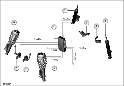
1 |
VDM control unit |
2 |
Shock absorber with damper satellite, rear right (EDCSHR) |
3 |
Height-level sensor, rear right |
4 |
Height-level sensor, rear left |
5 |
Shock absorber with damper satellite, rear left (EDCSHL) |
6 |
Shock absorber with damper satellite, front left (EDCSVL) |
7 |
Height-level sensor, front left |
8 |
Height-level sensor, front right |
9 |
Shock absorber with damper satellite, front right (EDCSVR) |
|
|
F-CAN |
Chassis CAN |
FlexRay |
Sub-bus |
PT-CAN |
Powertrain CAN |
|
|
EDC means: Electronic Damper Control
The vertical dynamics management (VDM) is an enhancement of the continuous Electronic Damper Control (EDC-K) from the E65. VDM is composed of a central control unit and 4 intelligent damper satellites firmly connected to the shock absorbers.
As data line, the data bus FlexRay has been implemented for the first time.
The following components are described for vertical dynamics management:
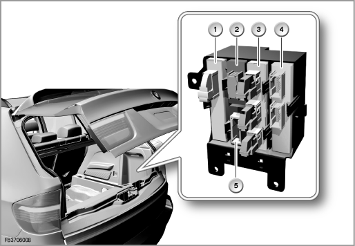
The VDM control unit is fitted on the device carrier in the rear right of the luggage compartment.
Index |
Explanation |
Index |
Explanation |
|---|---|---|---|
1 |
Comfort Access (CA) |
2 |
Trailer Module (AHM) |
3 |
Park Distance Control (PDC) |
4 |
Vertical dynamics management (VDM) |
5 |
Electronic Height Control (EHC) |
|
|
The VDM enhances on-road comfort. Greater on-road comfort is achieved when the vehicle body moves vertically as little as possible: neither due to excitation of the vehicle from the road (irregularities, joins) nor on cornering.
The VDM control unit specifies how the damper satellites are to activate the shock absorbers (individual damping force for each wheel). To this end, the VDM control unit is connected to the damper satellites via the very fast FlexRay data bus.
With a data transfer rate of 10 MBit/s, FlexRay is significantly faster than the data buses deployed nowadays in motor vehicles (in the area of body and drive or chassis). FlexRay supports not only the greater bandwidth but also data interchange with real-time capability. FlexRay can be configured as error-tolerant.
There are 4 damper satellites:
The damper satellites electronically control the damping forces. The damper satellites and the EDC valves are inseparably connected to the shock absorbers. Each damper satellite contains its own vertical-acceleration sensor. The damper satellites have the following tasks (among others):
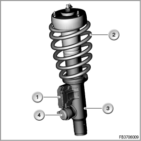
Damper satellite: for example on front axle, front left
Index |
Explanation |
Index |
Explanation |
|---|---|---|---|
1 |
Damper satellite, front left (EDCSVL) |
2 |
Steel springs |
3 |
Shock absorber |
4 |
EDC valve |
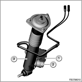
Damper satellite: for example rear axle, rear right
Index |
Explanation |
Index |
Explanation |
|---|---|---|---|
1 |
Damper satellite, rear right (EDCSHR) |
2 |
EDC valve |
3 |
Shock absorber |
|
|
There are the following 4 height-level sensors:
The 4 height-level sensors are connected to the VDM control unit. The height-level sensors deliver dynamic information on the height of the vehicle body to the VDM control unit. The vertical dynamics management uses this to calculate the body movements as well as wheel accelerations.
In addition, the sensors deliver the information to the automatic headlight vertical aim control.
The double height-level sensors on the rear axle deliver the signal not only to the VDM control unit but also to the EHC control unit. The double height-level sensors bear the lettering ”double” on the housing.
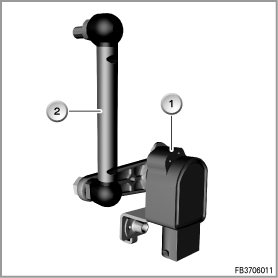
Height-level sensor: for example on front axle, front left
Index |
Explanation |
Index |
Explanation |
|---|---|---|---|
1 |
Height-level sensor |
2 |
Jointed rod |
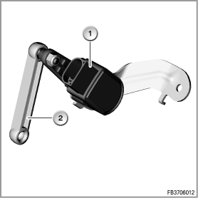
Height-level sensor: for example rear axle, rear left
Index |
Explanation |
Index |
Explanation |
|---|---|---|---|
1 |
Height-level sensor |
2 |
Jointed rod |
The sport button is located in the centre console behind the gear selector switch (GWS). Operation of the sport button changes the damping characteristics:
Comfort <-> Sport.
The sport button is electrically connected at the gear selector switch (GWS). The GWS is a separate control unit. The signal is then output on the PT CAN.
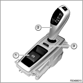
Index |
Explanation |
Index |
Explanation |
|---|---|---|---|
1 |
Parking brake button |
2 |
Gear selector switch (GWS) |
3 |
Sport button |
|
|
A control LED in the SPORT button indicates the activated sport program. ”SPORT” is also displayed on the LCD display in the instrument cluster.
The following other control units deliver signals for the vertical dynamics management:
The ARS control unit delivers the lateral acceleration on the PT-CAN to the VDM. The VDM control unit requires the signal as a substitute value.
The DSC control unit delivers the driving speed as well as brake pressure on the PT-CAN to the VDM.
The SZL delivers the steering-angle-sensor signal on the F-CAN to the VDM (advance detection of cornering).
The engine management system delivers the signal ”Engine running”. The signal is transferred across the PT CAN.
The JBE delivers the terminal status. The JBE is also the gateway between the PT-CAN and K-CAN.
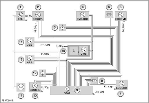
Index |
Explanation |
Index |
Explanation |
|---|---|---|---|
1 |
Steering column switch cluster (SZL) |
2 |
Damper satellite, front left (EDCSVL) |
3 |
Height-level sensor, front left |
4 |
Digital Engine Electronics /or Digital Diesel Electronics |
5 |
Height-level sensor, front right |
6 |
Damper satellite, front right (EDCSVR) |
7 |
Damper satellite, rear right (EDCSHR) |
8 |
Height-level sensor, rear right |
9 |
VDM control unit |
10 |
Damper satellite, rear left (EDCSHL) |
11 |
DSC sensor |
12 |
Height-level sensor, rear left |
13 |
Active roll stabilisation (ARS: Dynamic Drive) |
14 |
Junction box electronics (JBE) |
15 |
Gear selector switch with Sport button |
|
|
The following system functions are described for vertical dynamics management:
To dampen the wheel movements and body movements, the motion of the vehicle is monitored. Here, the following axes are included:
The following signals, e.g., are used for monitoring:
The signals are used to calculate the current driving situation.
For the vehicle vertical axis, the control of the damping is divided into 'comfort' and 'safety'.
The vertical dynamics management damps the body movements with regard to comfort.
The vertical dynamics management damps the wheel accelerations with regard to safety. At the same time, it must be ensured that the wheels do not lose contact with the road surface. Depending on the situation, optimised vertical force must be transferred.
The vertical dynamics management also takes account of steering angles (e.g. transition from straight-ahead driving into a curve). If a rapid enlargement of the steering angle is detected, the VDM control unit concludes that cornering is about to begin. This means that the shock absorbers can be activated accordingly in advance. In doing so, the vertical dynamics management supports active roll stabilisation (ARS). This means that the VDM contributes to reducing the rolling motion of the vehicle.
The vertical dynamics management also detects braking and acceleration. To achieve this, the DSC provides the brake pressure and longitudinal acceleration signals. Excessive brake pressure normally leads to a pitching motion of the vehicle. The VDM counteracts this pitching motion with a harder setting of the front shock absorbers. This also counteracts the pitching motion of the vehicle on accelerating.
Depending on the selected damping characteristics (comfort or sport via sport button), the level of the damping force is adapted by the VDM control unit. Independently of this, there is maximum driving safety in critical driving situations despite the selected comfort program.
Depending on the type of fault that has occurred, the fail safe takes effect in 3 stages:
Index |
Explanation |
Index |
Explanation |
|---|---|---|---|
1 |
Check Control message |
|
|
Important! On replacement of the shock absorbers, specify the installation location.
The shock absorbers, the damper satellites and the EDC valve form a unit that can be replaced entirely. When ordering a new component, the type of vehicle and installation location (e.g. front left) must be specified. There are dependencies with regard to: engine version, suspension as well as optional extras (e.g. 3rd row of seats).
Note: a number of fault code memories in the vertical dynamics management.
The VDM control unit only its own faults in its own fault code memory. Faults in the damper satellites are stored in their own fault code memory. This is why not only the fault code memory of the VDM control unit but also that of the damper satellites must be read out in the event of a fault. It must be possible for the BMW diagnosis system to reach the damper satellites. This is why the VDM control unit also works as the gateway for diagnosis between the PT-CAN and FlexRay.
Important! Run an adjustment of the height-level sensors.
After replacement of the VDM control unit as well as of a height-level sensor, the adjustment values of the height-level sensors must be relearned. The service function ”ride-height-calibration” on the BMW diagnosis system must be used.
Important! Run an adjustment of the vertical-acceleration sensors.
After replacement of one or several damper satellites, adjustment of the vertical-acceleration sensors must always be carried out. On the BMW diagnosis system, use the service function ”Vertical-acceleration sensor adjustment”.
The vehicle must be stationary on an even surface.
After replacement, the VDM control unit must be recoded.
The vertical dynamics management is activated under the following conditions:
No liability can be accepted for printing or other errors. Subject to changes of a technical nature