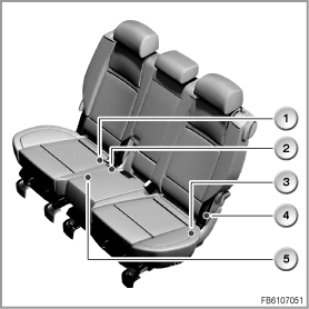
The interlock of the second row of seats is monitored by a number of microswitches in the E70. The micro-switches are fitted in the second row of seats. The micro-switches ensure that the locked bench seat does not come loose without being noticed. This enhances the protection against injury for the occupants.
The following components are described for interlock of the second row of seats:
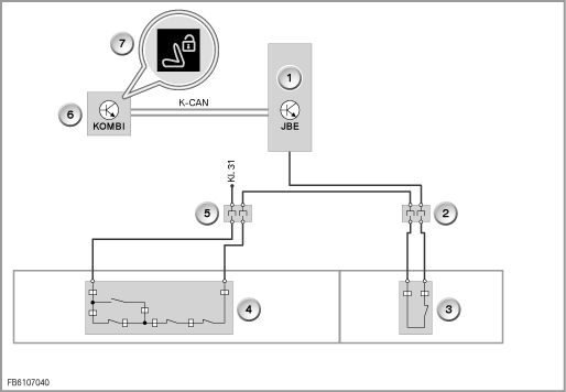
The micro-switches of the second row of seats are fitted in the large and small half of the seat. There are four micro-switches in the large half of the seat. The small half of the seat is monitored with one micro-switch. When the halves of the seat are properly locked, an earth signal is forwarded to the JBE. If the earth signal is interrupted, the junction box electronics (JBE) detects that the second row of seats is not properly locked.
The instrument cluster receives its information from the junction box electronics (JBE) via the K-CAN. If the JBE sends the information regarding a second row of seats that is not properly locked, the instrument cluster issues a suitable Check Control message. This message indicates to the driver that the row of seats is not properly locked. This indicates to the driver that there is an increased risk of injury to occupants.
The JBE is the monitoring control unit for the interlock in the second row of seats. The JBE receives an earth signal via the micro-switches. If the earth signal is interrupted, the JBE detects that the second row of seats is not properly locked. If a row of seats is not properly locked, the JBE sends information to the instrument cluster via the K-CAN.

Second row of seats in the E70
Index |
Explanation |
Index |
Explanation |
|---|---|---|---|
1 |
Micro-switch in small half of the seat, interlock in the seat substructure |
2 |
Micro-switches in the large half of the seat, interlock inside |
3 |
Micro-switches in the large half of the seat, interlock outside |
4 |
Micro-switches in the large half of the seat, backrest outside |
5 |
Micro-switches in the large half of the seat, seat cushion mounting inside |
|
|

Block circuit diagram E70
Index |
Explanation |
Index |
Explanation |
|---|---|---|---|
1 |
Junction box electronics (JBE) |
2 |
Seat connector, right |
3 |
Micro-switch, second row of seats, right |
4 |
Micro-switch, second row of seats, left |
5 |
Seat connector, left |
6 |
Instrument cluster |
7 |
Check Control message (back seat not locked!) |
|
|
The following system functions are described for the interlock of the second row of seats:
Micro-switches are installed in the backrest and seat cushion to monitor the large half of the seat. There is only one micro-switch on the outside of the backrest. Two micro-switches are located in the seat substructure, inside and outside. Another micro-switch is located on the seat cushion mounting in the seat substructure. When folded down, the backrest is not locked. When the halves of the seat are properly locked, an earth signal is forwarded to the JBE.
The following seat states are monitored:
The small half of the seat is monitored with only one micro-switch. The micro-switch is located on the mechanical interlock on the inside of the seat substructure. When the small half of the seat is properly locked, the switch is closed.
When the junction box electronics (JBE) detects that the second row of seats is not properly locked, the instrument cluster receives this information. The instrument cluster issues a Check Control message. The message ”Back seat not locked!” is intended to indicate to the driver that there is an increased risk of injury to occupants.
No liability can be accepted for printing or other errors. Subject to changes of a technical nature