The turning lights are only available in conjunction with the adaptive headlight optional extra. The turning lights supplement the adaptive headlight to illuminate the areas in front of and beside the vehicle.
The following components are described for the turning lights:
The turning light can only be activated when the light switch is in position ”A”. For automatic driving light control, the light switch has a green indicator light. If a system error is detected, the indicator light starts to flash. The light switch is directly connected to the footwell module (FRM).
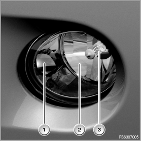
A special fog lamp is necessary for the turning light. The fog lamp contains a reflector for the turning light. As soon as the fog lamp is switched on, the light of the fog lamp bulb reaches the reflector for the turning lights. The reflector is specially shaped and it reflects the light in the turning zone. From the outside, the fog lamp with turning light function can be recognised in that the reflector is fully chrome-plated.
The RLSS is located on the windscreen in the base of the interior rearview mirror. The RLSS detects dusk or darkness. When the threshold value is exceeded, the RLSS sends a message to the roof function centre (FZD). The RLSS is connected with the FZD via the LIN bus. The FZD forwards this message to the footwell module (FRM) via the K-CAN.
The turn indicator-high-beam switch is located in the SZL. The turn indicator-high-beam switch sends its signals to the SZL. The SZL sends the received signals on to the footwell module (FRM).
Control for the turning lights is handled by the FRM. The FRM also controls the indicator light in the light switch. The FRM receives all the conditions required for switch-on directly or via the K-CAN. The FRM is located at the side of the footwell on the driver's side, under the instrument panel.
The JBE is responsible for the power supply. The JBE is connected to the FRM via the K-CAN. The JBE is located below the instrument panel in the passenger footwell.

Structure of the fog lamp on the E70
Index |
Explanation |
Index |
Explanation |
|---|---|---|---|
1 |
Reflector for turning light |
2 |
Reflector for fog lamp |
3 |
Fog lamp bulb |
|
|

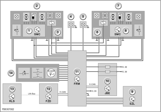
Block circuit diagram E70
Index |
Explanation |
Index |
Explanation |
|---|---|---|---|
1 |
Stepper motor controller (SMC), left |
2 |
Main headlight, left |
3 |
Xenon-headlight control unit, left |
4 |
Front foglight, left |
5 |
Front foglight, right |
6 |
Xenon-headlight control unit, right |
7 |
Main headlight, right |
8 |
Stepper motor controller (SMC), right |
9 |
Steering Column Switch (SZL) |
10 |
Junction box electronics (JBE) |
11 |
Footwell module (FRM) |
12 |
Roof control panel |
13 |
Rain/light solar sensor (RLSS) |
14 |
Light switch |
The turning lights are not switched on and off suddenly. The turning lights are switched on and off and faded according to special time parameters. Depending on the country, the turning lights are switched on and off when cornering.
The following system functions are described for the turning lights:
If the vehicle is stationary, the turning lights will automatically be deactivated after a certain time, e.g. when waiting at traffic lights. However, the turning lights can be switched on again using the turn indicator / high-beam switch
The side of the turning lights to be activated depends on the following conditions:
Driving forwards
Backing up
Only US version:
If a defect in the turning lights is detected, the same Check Control messages as for the fog lamps apply.
No liability can be accepted for printing or other errors. Subject to changes of a technical nature