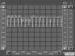
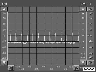
All oscilloscope images are reference values and may deviate depending on the image content!
Image signals R G B (red, green, blue)
Signal |
Video module |
On-board monitor |
R |
Pin 7 |
Pin 1 |
G |
Pin 5 |
Pin 3 |
B |
Pin 6 |
Pin 5 |
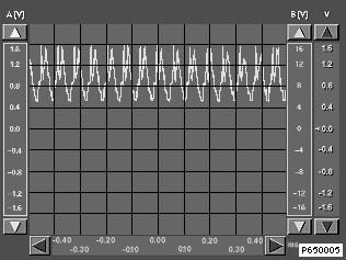
Image signals in TV mode
Ground LC display < Evaluate voltage range only ! >
Video module |
On-board monitor |
Pin 12 |
Pin 7 |