The glow system of the N47 4-cylinder diesel engine consists of the following components:
The first time the combustion preheating control unit is switched on, the electrical resistance of the glow plugs is evaluated at the start of the glow process. A glow plug that is already hot has a significantly higher resistance than a glow plug that is cold. If the resistance leads to the detection of hot glow plugs, the glow plugs are supplied with less energy at the start of glowing. If, on the other hand, cold glow plugs are detected, the glow plugs are supplied with the maximum energy at the start of glowing. This function is referred to as dynamic repeat glowing. It prevents a glow plug that is already hot from being overheated by a second glow process that follows shortly after the first glow process, thus supplying too much energy.
To check the glow system, there are two adapter leads:
- 1-pin, order number 13 6 470
- 12-pin, order number 13 6 460
The required glow plug temperature is determined by the DDE control unit on the basis of the following operational parameters:
To activate glowing, the DDE sends the required glow plug temperature to the combustion preheating control unit.
Across the LIN bus, the DDE also sends the following operating values to the combustion preheating control unit:
The combustion preheating control unit uses these three operating values to determine the required current for the glow plugs and supplies the glow plugs with current.
Glowing is activated in various operating states:
Coolant temperature [°C] |
< -35 |
-25 |
-20 |
-5 |
0 |
5 |
30 |
>30 |
Preglow time [s] |
3.5 |
2.8 |
2.8 |
2.1 |
1.6 |
1.1 |
1.1 |
0 |
Hidden glowing is triggered a maximum of four times and then only enabled again with the engine start.
The DDE control unit and combustion preheating control unit communicate across the LIN bus.
The LIN bus is a bidirectional data interface based on the master-slave principle. The DDE control unit is the master controller.
The following components are described for the glow system:
The combustion preheating control unit contains the power output stages for activation of the glow plugs. The combustion preheating control unit does not have its own fault code memory. Faults in the glow system that are detected by the combustion preheating control unit are reported to the DDE by the combustion preheating control unit across the LIN bus. The faults are then stored in the DDE fault code memory.
If the permitted operating temperature of the combustion preheating control unit is exceeded, the combustion preheating control unit shuts down any glow process to prevent damage.
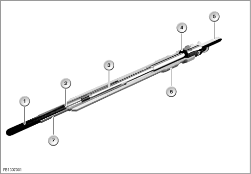
The ceramic glow plugs are designed for a voltage of 7.0 to 10.0 Volts. During glowing, on-board supply voltage can be applied briefly for rapid heating up. To maintain the glow plug temperature, the glow plugs are supplied with a PWM signal. This sets an effective voltage at the glow plugs that is lower than the on-board supply voltage.

Fig. 1: sectional view of ceramic glow plug
1 |
Ceramic heating element |
5 |
Round connector |
2 |
Positive terminal connection |
6 |
Thread |
3 |
Connection bolt |
7 |
Support tube |
4 |
Gasket |
|
|
Important!
The ceramic glow plugs are sensitive to impacts and bending. Glow plugs that are dropped can be damaged.