
The gear selector switch (selector lever) enables the engagement of the individual drive positions or gears (Steptronic). The selector-lever position is transferred to the gearbox by means of a cable. The engaged drive position is shown visually via the shift-indicator illumination.
Vehicles with rocker switches
In addition to the sequential gear selection by means of the selector lever, the gears can also be shifted at the steering wheel with 2 rocker switches (vehicle-specific).
To upshift, briefly pull one of the two rocker switches.
To downshift, briefly press one of the two rocker switches.
The selector lever is built into the centre console. The selector-lever cover contains the illuminated display for the selector-lever position. The engaged drive position is backlit on the gearshift diagram. The background light is activated by the wiping contact on the selector lever.
An interlock prevents inadvertent shifts to selector-lever positions ”R” and ”P”. To cancel the interlock, press the button on the front of the selector lever knob.
Index |
Explanation |
Index |
Explanation |
|---|---|---|---|
1 |
Illuminated display for the selector-lever position |
2 |
Selector-lever cover |
3 |
Button |
4 |
Selector lever |
The selector lever has the positions
The following system functions are described:
The parking lock blocks the gearbox output shaft. The vehicle is secured against rolling away. The parking lock is designed in such a way that on upward or downward inclines of up to 32 % a secure hold is always ensured.
The parking lock is engaged purely mechanically with the vehicle stationary using the selector lever (Bowden cable from selector lever to the mechatronics module).
The selector lever is interlocked in the positions ”P” and ”N” by an electromagnet. The electromagnet is activated by the EGS control unit.
The selector lever interlock is engaged when selector-lever position ”P” or ”N” is detected and the ignition (terminal 15) is ON.
A position change from selector-lever position ”P” or ”N” is only possible at a driving speed below 5 kph and when the brake is operated at an engine speed below 2500 rpm.
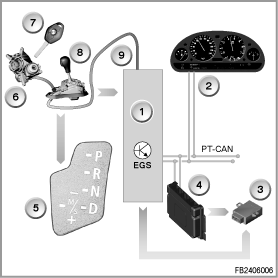
Index |
Explanation |
Index |
Explanation |
|---|---|---|---|
1 |
EGS control unit integrated in the mechatronics module |
2 |
Instrument cluster (KOMBI) |
3 |
Electronic immobiliser (EWS) |
4 |
Digital Engine Electronics (DME) |
5 |
Display of the selector-lever position with gearshift diagram in the selector-lever cover |
6 |
Bowden cable for withdrawal lock of the ignition lock |
7 |
Ignition lock with withdrawal lock (interlock) |
8 |
Selector lever |
9 |
Bowden cable for gear position switch with gearbox position sensor and parking lock |
PT-CAN |
Powertrain CAN |
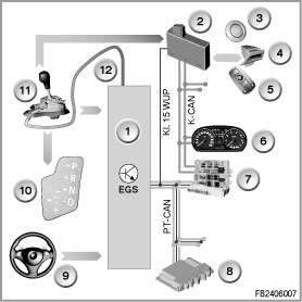
Index |
Explanation |
Index |
Explanation |
|---|---|---|---|
1 |
EGS control unit integrated in the mechatronics module |
2 |
Car Access System (CAS) |
3 |
START-STOP button |
4 |
Insert compartment with withdrawal lock (interlock) |
5 |
Remote control |
6 |
Instrument cluster (KOMBI) |
7 |
Junction box electronics (JBE) |
8 |
DME (Digital Engine Electronics) or DDE (Digital Diesel Electronics) |
9 |
Steering wheel with rocker switches |
10 |
Display of the selector-lever position with gearshift diagram in the selector-lever cover |
11 |
Selector lever |
12 |
Bowden cable for gear position switch with gearbox position sensor and parking lock |
K CAN |
Body CAN |
Terminal 15 WUP |
Wake-up line (terminal 15 wake up) |
PT-CAN |
Powertrain CAN |
|
|
If the rocker switches are used ti make a shift in selector-lever position ”D”, the automatic gearbox switched to the manual mode.
If no gear is shifted within a time span of 6 seconds or there particularly high acceleration, the automatic gearbox returns to the automatic mode.
The selector lever can only be tilted from position ”D” into the gearshift gutter ”M/S”. For this operation, the EGS control unit must simultaneously detect the signals ”gearshift gutter M/S” and ”Position D”.
No liability can be accepted for printing or other errors. Subject to changes of a technical nature