Trailer module
Trailer module
The functional description describes the trailer module for the following vehicles:
- E81, E87, E90, E91, E92, E93 (BMW 1 Series, 3 Series)
- E60, E61, E63, E64 (BMW 5 Series, 6 Series)
- E65, E66, E67, E68 (BMW 7 Series)
- E70 (BMW X5)
- R56 (MINI)
The trailer module is a secondary control unit for the footwell module (R55, E70) or light module. At the moment, two different trailer modules are installed. The AHM3 is the version that has been deployed to date. The AHM3+ is the revised version. Essentially, it differs from the AHM3 with regard to the following characteristics:
- 2 lines and fuses for the power supply, enabling more electrical power output to be provided for the trailer lighting.
- Articulated ball head with electrical monitoring of the interlock of the ball head by the control unit for the trailer interlock. Status report to the trailer module.
- Storage of the faults detected by the control unit for the trailer interlock
The trailer module separates the current circuits of the trailer from the circuit of the towing vehicle. The control unit also reports the status of the articulated ball head to the trailer module for the trailer interlock.
The AHM3+ will be fitted as volume production launch on the E70 and R55. In all the other model series mentioned above, the AHM3+ will be fitted as of 09/ 06.
Observe the following differences with regard to fitting and the function of the trailer module as well as the trailer coupling:
- MINI
The trailer module will be fitted in the R56 version as a special accessory. The trailer module delivers the electrical energy for the rear bicycle rack offered as a special accessory. A trailer coupling is not offered for the R56.
- BMW
The trailer module is fitted if the vehicle is equipped with a trailer coupling. The trailer coupling can be firmly installed or removable. Moreover, it is also possible to fit a semi-electric or fully electrical articulated ball head.
Brief description of components
Alongside a microprocessor, the trailer module consists essentially of overload-resistant sense FET power circuit breakers for the trailer power circuits.
The sense outputs of the power circuit breakers enable monitoring of the power circuits for excess current or wire breaks. The power circuit breakers are activated via CAN messages.
Also implemented is an input for direct activation of the brake light by the brake light power circuit of the towing vehicle (hard-wired). The emergency function guarantees the function of the brake light on failure of the CAN bus. The identical function is also installed for the tail lights of the trailer.
The following control units are involved in the functions of the trailer module:
- AHM trailer module
The trailer module controls and monitors the current circuits of the trailer. The trailer module also separates the current circuits of the trailer from the vehicle network of the towing vehicle. In the event of system errors, the trailer module creates the Check Control messages.
- Control unit for the trailer coupling release
The control unit is connected to the vehicle network by a 16-pin connector. The control unit has no direct connection to the bus system. The trailer coupling release is operated using a button in the luggage compartment. The control unit is installed in the luggage compartment in the device carrier. The control unit is neither programmable nor self-diagnosable.
- CAS: Car Access System
The CAS control unit delivers the signal for terminal 15. This signal is monitored by the trailer module and the control unit of the trailer coupling release.
- JBE: junction box electronics
The junction box supplies the trailer module with voltage (terminal 30g). Moreover, the junction box also supplies the trailer coupling release with voltage.
The trailer module detects overvoltage and undervoltage in the vehicle network. Outside the valid range of 9 to 15 Volt, functions that are not relevant to safety are switched off. For example, the trailer coupling release cannot be activated with undervoltage or overvoltage.
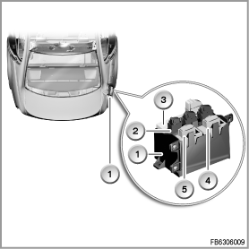
The graphic shows the E90
Index
|
Explanation
|
Index
|
Explanation
|
1
|
Device carrier
|
2
|
Park Distance Control (PDC)
|
3
|
Control unit for comfort access
|
4
|
Control unit for the trailer coupling release
|
5
|
Trailer Module
|
|
|
System functions
The following system functions are described for the trailer module:
- Trailer lighting
- Trailer detection
- Trailer coupling release
Trailer lighting
The trailer lighting runs the following functions:
- Brake light
- Sidelights
- Indicating, hazard warning lights, crash alarm hazard warning lights, DWA alarm flashing
- Rear fog light
- Reversing lights
The trailer module activates the individual lamp electrical circuits of the trailer. The implemented functions for the trailer lighting are described in the following section.
- Brake light
The brake light on the trailer is switched on when the service brake in the towing vehicle is operated.
- Sidelights
The sidelights on the trailer are activates when the light switch on the towing vehicle is in the 'sidelights' or 'dipped beam' position. When the Automatic Light Control is activated, the sidelights of the trailer are switched on depending on the level of brightness.
- Indicating, hazard warning lights, crash alarm hazard warning lights, DWA alarm flashing
For turn indicating, there are two indicating functions implemented by the trailer module.
- One-touch indicating: When the indicator / high-beam switch is touched briefly, the turn-indicator lights are activated briefly. The number of flashing pulses here depends on the coding of the towing vehicle. One-touch indicating can be used e.g. for changing lanes.
- Continuous flashing: When the indicator / high-beam switch is 'overpressed' beyond the resistance point, the turn-indicator lights are activated with the function ”continuous flashing”. Continuous flashing is the turn indicator function, e.g. before turning right or left.
The flash frequency is adapted to the flash frequency of the towing vehicle by the trailer module. At the start of each flashing period, CAN messages are sent in cycles. These messages serve to synchronise the flash frequency between the towing vehicle and trailer. If a turn-indicator light on the vehicle or trailer is defective, the flash frequency is doubled (defective flashing).
The following additional functions of the flashing trailer lights are implemented by the trailer module:
- Hazard warning lights: The driver switches on the hazard warning lights using the hazard-warning switch. The trailer flashes along with the towing vehicle if the hazard warning lights are activated.
- Crash alarm hazard warning lights: If the ISIS system detects a crash, the hazard warning lights are switched on (depending on the coding). The hazard warning lights can be switched off again using the hazard-warning switch. The trailer flashes along with the vehicle if the hazard warning lights are activated in a crash alarm.
- DWA alarm hazard warning lights: the hazard-warning switch in the towing vehicle does not flash. The trailer flashes along with the vehicle if the hazard warning lights are activated in a DWA alarm. However, the trailer does not provide acknowledgement flashes on activating / arming the anti-theft alarm system.
- Rear fog lamp:The rear fog lamp is switched on with
- terminal 15 On and
- the light switch of the towing vehicle in the dipped beam position
- the rear fog lamp activated by the switch.
or with
- terminal 15 On and
- the light switch of the towing vehicle in 'sidelights' position and
- the fog light activated and
- the rear fog lamp activated by the switch.
The rear fog lamp is switched off again when
- the rear fog lamp is deactivated by the switch
- terminal 15 OFF, or
- light switch OFF.
- Reversing light
The reversing light is switched on when reverse gear is engaged on the towing vehicle and terminal 15 is ON. The reversing lights are switched on with a delay of a fraction of a second to avoid their flashing during gear changes.
Trailer detection
The trailer module detects a trailer as connected when at least two loads (cold measurement) are detected at the lighting outputs. The trailer module then reports the status ”Trailer connected”. This status report is implemented in the towing vehicle in a number of control units. For example, the Park Distance Control is disabled at the rear. Moreover, to prevent the driver from being dazzled, the reversing light and the rear fog lamp of the towing vehicle are disabled.
Trailer coupling release
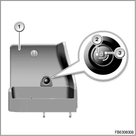
The electrical trailer coupling release is a component of the optional extra 'trailer coupling with articulated ball head'. This optional extra is offered for the E70 and E90, 91, 92, 93. The trailer coupling release is operated using a button in the luggage compartment.
The graphic shows the E90
Index
|
Explanation
|
Index
|
Explanation
|
1
|
Luggage compartment trim
|
2
|
Indicator lamp (LED red and green)
|
3
|
Button for the trailer coupling release
|
|
|
There is a two-colour LED for the indicator lamp in the button. The following signals are possible:
- The LED lights up green:
the trailer coupling is in the locked end position.
- The LED flashes slowly red (2 Hz):
the trailer coupling is not in the locked end position.
- The LED flashes quickly red (4 Hz):
- The drive has been activated for longer than 4 seconds.
- The current necessary for the release function drive has not been reached (12 Amperes).
The drive for the trailer coupling release is attached to the release unit. The ball head can only be released if the following conditions have been met:
- Terminal 15 OFF
- Boot lid open
The trailer coupling can be released as of terminal 30g ON. For it to be released, the following signal states must be present:
- Terminal 30g: high signal
- Button for the trailer coupling release: low signal
- Terminal 15: low signal
- Luggage compartment contact switch: low signal
- Micro-switch for drive of trailer coupling release, output 1: low signal
- Micro-switch for drive of trailer coupling release, output 2: high signal
After a successful check of the signal states, the DC motor for the trailer coupling is activated. As long as the ball head is not locked into the end position, a sound signal is issued. A Check Control message is also displayed.
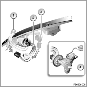
The graphic shows the E90
Index
|
Explanation
|
Index
|
Explanation
|
1
|
Ball head articulated outwards
|
2
|
Unlocked intermediate position
|
3
|
Ball head articulated inwards
|
4
|
Drive for the trailer coupling release
|
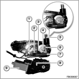
The drive for the trailer coupling release consists of a direct current motor and a reduction gear. The following components are integrated in the release unit:
- Micro-switch with slide and compression spring
- Drive disk for the micro-switch
- Drive disk for the release lever
- Release lever
The graphic shows the E90
Index
|
Explanation
|
Index
|
Explanation
|
1
|
Compression spring
|
2
|
Micro-switch
|
3
|
Drive disk for the slide
|
4
|
Drive shaft
|
5
|
Release lever
|
6
|
Drive disk for the release lever
|
7
|
Slide
|
8
|
Reduction gear
|
9
|
DC motor
|
|
|
Notes for Service department
The following information is provided for service of the trailer module:
General information
If the power supply is interrupted during operation of the trailer coupling release, various signal states can be lost.
Once the power supply is available again, the button for the trailer coupling release must be pressed for 5 seconds. This switches on the drive (emergency actuation).
If the power supply has been interrupted, the trailer coupling cannot be released.
Diagnosis instructions
The trailer module detects the following faults:
- Checksum fault of the various memories and watchdog reset
- Faults of the CAN drivers
- Wire faults of the CAN interface and of the brake light input
- Wire fault of all outputs with short circuit and wire break
- Undervoltage / overvoltage and implausibility of the control unit voltage in comparison with the on-board supply voltage
- Implausibility of a CAN message ”Braking” compared to the hard-wired brake light input at the control unit
- Implausibility of the sense values of the lighting outputs of the control unit
The trailer module detects a fault in the trailer coupling release through a missing 'Alive' signal. A Check Control message is output.
A Check Control message is also issued if the ball head has not been locked at terminal 15 ON.
Faults on the lamp outputs of the trailer module are output as Check Control messages.
The drive of the trailer coupling release can be replaced separately.
Notes on coding / programming
Coding
After installation of a trailer module, the control unit must be recoded. In doing so, observe the various national versions.
No liability can be accepted for printing or other errors. Subject to changes of a technical nature


