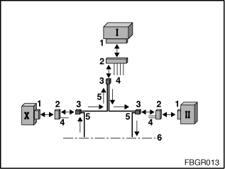
The MOST (Media Oriented Systems Transport) network uses a ring bus for data communication between the various control units. Signal transmission is by means of fibre-optic cable. Data transmission on the ring bus takes place in one direction only. On the MOST ring, messages can only be transmitted provided the bus ring is complete and fully functional. If there is a fault in the MOST ring, the system can only communicate with the head unit. This is possible because the control unit is directly connected to the K-CAN data bus. There is a transmission and a reception module (transmitter and receiver) as a unit in each MOST control unit for connecting to the MOST bus. The unit has an integrated transmit and receive diode. The optical testing and programming system can be used to test the transmitter and receiver of a control unit.
If there is a ring fault (defect between two control units), the following fault profiles can occur:
The above faults can also occur in combination with each other. When there is a ring fault, the first task is to locate the two control units between which the ring fault has occurred. This is established using the ring fault diagnosis. In order to be able to identify the fault precisely, ring fault diagnosis must be followed by a check of the power supply. If the power supply is OK, the defect can only be established using the optical test. The test program for the optical test on the MOST bus (or ring fault diagnosis, as the case may be) can be found under function selection: Body, Bus Functions, MOST Functions and Optical Test (or Ring Fault Diagnosis).
Transmission direction in the MOST ring
Transmission of messages is from the head unit towards the CD changer, amplifier, ..., video module, ... and back to the head unit.
In the MOST ring, the sockets (1) and connectors (2) for each of the MOST control units are different. Only the two-pin fibre-optic cable connector (3) is the same for all MOST control units. This means that two adapters are required for the optical test on the MOST bus.

Fig. 1: Overview of the plug-in connections from the MOST ring
I: Head unit |
II, X: MOST control unit according to car equipment |
1: Socket for control unit |
2: Connector for control unit |
3: Two-pin fibre-optic cable connector pinned from control-unit plug (2) |
4: Power supply and other cables |
5: Optical fibres |
6: Other MOST control units according to car equipment |
The optical testing and programming system
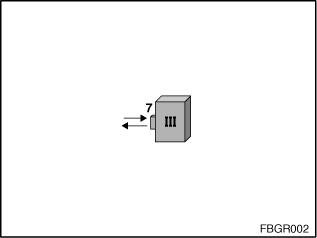
Fig. 2: Optical testing and programming system (III)
III: Optical testing and programming system |
7: Socket for mounting the MOST adapter |
The optical testing and programming system (MOST section) has a socket for connection to the MOST adapters.
For the optical test of a control unit (or fibre-optic cable), the control unit (or fibre-optic cable) must be connected to the optical testing and programming system using an adapter. However, each adapter has a different attenuation value. So that these different attenuation values are taken into account in the optical test, calibration must be carried out before each optical test. During the calibration, there is also a check as to whether the adapter is OK. The various calibrations, depending on whether a MOST control unit or a fibre-optic cable is being tested, are shown below.
Calibration for the test of the MOST control unit:To test a MOST control unit, you need the MOST control unit cable (A1 = 663122 and 663121). For calibration, you connect the MOST control unit cable (A1) to:
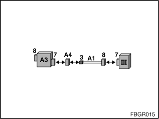
Fig. 3: Calibration for the test of the MOST control unit
III: Optical testing and programming system |
3: Two-pin fibre-optic cable connector |
7: Socket for mounting the MOST adapter |
8: Connector from MOST adapter or test loop |
A1: 663122 and 663121 |
A3: 663124 |
A4: 663125 |
|
Calibration for the test of the fibre-optic cable: To test the fibre-optic cable, the MOST wiring harness extension is required (A2 = 663123). For the calibration, the MOST wiring harness extension (A2) is connected to:
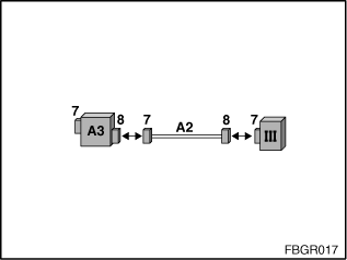
Fig. 4: Calibration for the test of the fibre-optic cable
III: Optical testing and programming system |
|
7: Socket for mounting the MOST adapter |
8: Connector from MOST adapter or test loop |
A2: 663123 |
A3: 663124 |
For the optical test of a control unit (or fibre-optic cable), the control unit (or fibre-optic cable) must be connected to the optical testing and programming system using an adapter. The two adapters required for this test are shown in the following.
Test of the MOST control unit:To test a MOST control unit, (II) the MOST control unit cable is required (A1 = 663122 and 663121). Procedure for testing a MOST control unit:
In order to disconnect the two-pin fibre-optic cable connector (3) from control unit connector (2), it might be required to disconnect the control unit connector (2) from the socket (1) first. Then run the operation as described under 1 to 3 and on completion connect control unit connector (2) with socket (1).
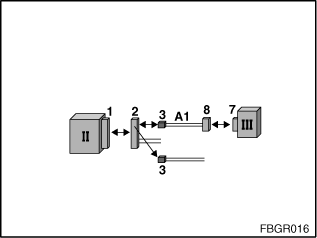
Fig. 5: Test of the MOST control unit
II: MOST control unit |
III: Optical testing and programming system |
1: Socket for control unit |
2: Connector for control unit |
3: Two-pin fibre-optic cable connector pinned from control-unit plug (2) |
7: Socket for mounting the MOST adapter |
8: Connector from MOST adapter |
A1: 663122 |
Test of fibre-optic cable: To test the fibre-optic cable, the MOST wiring harness extension (A2 = 663123) and plug housing are required (A4 = 663125). Procedure for testing the fibre-optic cable:
In order to disconnect the two-pin fibre-optic cable connector (3) from control unit connector (2), it might be required to disconnect the control unit connector (2) from the socket (1) first.
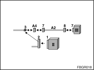
Fig. 6: Test of fibre-optic cable
II: MOST control unit |
III: Optical testing and programming system |
1: Socket for control unit |
2: Connector for control unit |
3: Two-pin fibre-optic cable connector pinned from control-unit plug (2) |
7: Socket for mounting the MOST adapter |
8: Connector from MOST adapter |
|
A2: 663123 |
A4: 663125 |
Note:
To test the fibre-optic cable, the two-pin fibre-optic cable must be disconnected from a MOST control unit and connected to the OPPS device. If, for example, you wish to test the fibre-optic cable between the amplifier and the video module, the fibre-optic cable must be disconnected from the video module and connected to the OPPS device.
If a fibre-optic cable is disconnected in the MOST ring, a red light flashes at the exit of the fibre-optic cable. The head unit attempts namely, with the fibre-optic cable disconnected, to wake up the MOST bus using the flashing light. To test the fibre-optic cable, the two-pin fibre-optic cable must be disconnected from a MOST control unit and connected to the OPPS device. However, the test of the fibre-optic cable only leads to a correct conclusion if an exit flashes when the fibre-optic cable is disconnected.
It is namely the case when testing the fibre-optic cable that if, for example, a MOST control unit in the MOST ring or a second section of fibre-optic cable in front of the tested fibre-optic cable in the MOST ring is defective, then the MOST ring cannot be optically closed. This is why the fault ”no flashing light” at the exit of the fibre-optic cable can have the following causes:
In order to localise the cause of the fault, perform the following steps:
Disconnect another fibre-optic cable in front of the fibre-optic cable in the MOST ring (where there is no flashing light at the exit) and check whether you can see a flashing light at the exit:
Note:
If the display of the light output fluctuates during the test of the fibre-optic cable, it is highly likely that there is another defective point after the tested fibre-optic cable in the MOST ring. The cause is that the ring is not closed and there is thus no continuous light in the ring, rather pulsed light (if the MOST ring is interrupted, the Radio 2 (or Multi Audio System Controller or Car Communication Computer) attempts to wake up the MOST bus using a flashing light).