As of 09/06, the multi-stage turbocharging familiar from the M57TUTOP will also be deployed on the M57TU2. It will be deployed for the first time in the E90/91 and E83.
Index |
Explanation |
Index |
Explanation |
|---|---|---|---|
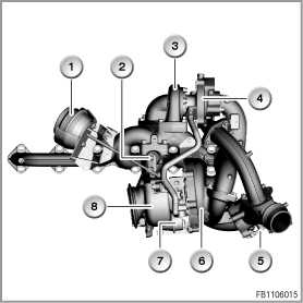
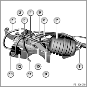
1 |
Partial-vacuum canister for turbine control flap |
2 |
Turbine control flap |
3 |
Small turbine |
4 |
Small compressor |
5 |
Compressor bypass plate |
6 |
Large compressor |
7 |
Partial-vacuum canister, wastegate valve |
8 |
Large turbine |
Turbocharger group, view from the left
Index |
Explanation |
Index |
Explanation |
|---|---|---|---|
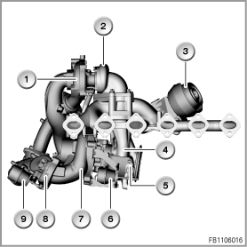
1 |
Small compressor |
2 |
Small turbine |
3 |
Partial-vacuum canister for turbine control flap |
4 |
Large turbine |
5 |
Wastegate valve |
6 |
Partial-vacuum canister, wastegate valve |
7 |
Large compressor |
8 |
Compressor bypass plate |
9 |
Partial-vacuum canister for compressor bypass plate |
|
|
The size of the turbocharger used has a decisive influence on the operating characteristics of the engine (power output and response characteristics). A small turbocharger has very good response characteristics on account of the low masses that have to be accelerated by the exhaust gas. On acceleration, the boost pressure is built up very quickly. This means the engine reacts with a very small delay.
The characteristics of a large turbocharger are different. On acceleration, the exhaust gas must accelerate large masses. The turbocharger - and thus also the engine - reacts more sluggishly on acceleration. However, if high final power output is desired, i.e high charge pressures and air throughputs are required, the large turbocharger has an advantage due to the greater cross sections.
For the two-stage turbocharging, both turbochargers are set up in line. First of all, the exhaust gas drives the small turbine, then the large turbine. On the fresh air side, the large compressor compresses the fresh air first, then the small compressor does the same.
The turbine control flap controls the distribution of the exhaust flow between the large and small turbines. The turbine control flap is adjusted pneumatically by a diaphragm can. The turbine control flap can be set variably. An electropneumatic pressure converter applies a partial vacuum to the diaphragm can.
The compressor bypass plate enables a bypass of the small compressor on the air side. The compressor bypass plate is adjusted pneumatically by the diaphragm can. The compressor bypass plate is either opened fully or closed fully. An electric switchover valve applies a partial vacuum to the diaphragm can.
When the nominal rating is reached, the wastegate valve is opened to prevent excessively high boost pressure. A portion of the exhaust gases is fed via the wastegate valve to the large turbine. The wastegate valve is adjusted pneumatically by a diaphragm can. The wastegate valve can be set variably. An electropneumatic pressure converter applies a partial vacuum to the diaphragm can.
The DDE has been enhanced for the activation. The DDE control unit activates the above-mentioned actuators for the two-stage charge.
For configuration of a turbocharger, there must always be a compromise between good response characteristics and high final power output. With the turbochargers used at BMW with variable turbine geometry, this disadvantage of the single-stage turbocharging is reduced, but is cannot be completely eliminated. With multi-stage turbocharging, the two turbochargers work together in such a way that optimised operating characteristics are achieved.
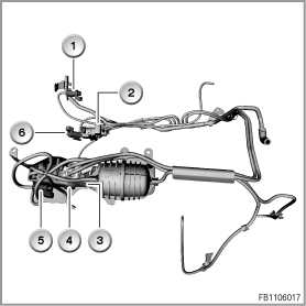
Index |
Explanation |
Index |
Explanation |
|---|---|---|---|
1 |
Electric switchover valve for swirl flaps |
2 |
Electropneumatic pressure converter for exhaust-gas recirculation |
3 |
Electropneumatic pressure converter for wastegate valve |
4 |
Electropneumatic pressure converter for turbine control flap |
5 |
Electric switchover valve for compressor bypass plate |
6 |
Electric switchover valve for engine mount |
Vacuum distributor, view from the left
Index |
Explanation |
Index |
Explanation |
|---|---|---|---|
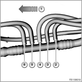
1 |
Driving direction |
2 |
Vacuum supply for swirl flaps |
3 |
Vacuum supply, engine mount |
4 |
Vacuum supply for exhaust-gas recirculation |
5 |
Vacuum supply, compressor bypass plate and turbine control flap |
6 |
Vacuum supply, wastegate valve |
Index |
Explanation |
Index |
Explanation |
|---|---|---|---|
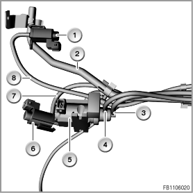
1 |
Vacuum supply, compressor bypass plate |
2 |
Vacuum supply, turbine control flap |
3 |
Vacuum distributor |
4 |
Vacuum supply, compressor bypass plate and turbine control flap |
5 |
Vacuum supply, wastegate valve |
6 |
Activation wire, wastegate valve |
7 |
Vacuum reservoir |
8 |
Vacuum supply, compressor bypass plate and turbine control flap |
9 |
Electropneumatic pressure converter for wastegate valve |
10 |
Electropneumatic pressure converter for turbine control flap |
11 |
Activation wire for turbine control flap |
12 |
Electric switchover valve for compressor bypass plate |
13 |
Activation wire for compressor bypass plate |
|
|
Index |
Explanation |
Index |
Explanation |
|---|---|---|---|
1 |
Electric switchover valve for swirl flaps |
2 |
Vacuum supply for brake booster |
3 |
Vacuum supply for exhaust-gas recirculation |
4 |
Activation wire for exhaust-gas recirculation |
5 |
Electropneumatic pressure converter for exhaust-gas recirculation |
6 |
Electric switchover valve for engine mount |
7 |
Activation wire for engine mount |
8 |
Vacuum supply for swirl flaps |