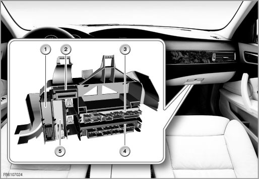
The buttons of the centre console switching cluster can be used to activate and deactivate various functions in the vehicle. In addition, the centre console switch cluster also controls the electrical steering column adjustment and the roller sunblind.
The following components are described for the centre console switch cluster:
The centre console switch cluster control module is located in the carrier behind the glove compartment. The control module sends the status of each button in the blocks on the driver's and passenger's side across the K-CAN to the control module responsible. The centre console switch cluster control module contains the software for activation of the electrical steering column adjustment and of the roller sunblind.

Index |
Explanation |
Index |
Explanation |
|---|---|---|---|
1 |
Centre console switch centre (SZM) |
2 |
Control electronics |
3 |
Body basic module (KBM) |
4 |
Body-gateway module (KGM) |
5 |
Comfort Access (CA) |
|
|
The control electronics circuit is located in the carrier behind the glove compartment. The control electronics circuit contains the power electronics for activation of the motors of the steering column adjustment and the roller sunblind motor.
The switch block for the driver and the switch block for the front passenger are located on the right and left of the ashtray in the centre console. Depending on the equipment version, there are switch blocks with 1, 2 and 3 rows.
The SPORT button is located in front of the gear selector switch. The SPORT button is connected directly to the centre console switch cluster control module.
The switch for steering-column adjustment is located on the left-hand side of the steering column. The switch for the steering column adjustment can be used to adjust the length and inclination of the steering column. It is activated via the steering column switch cluster (SZL).
The roller sunblind is located in the vehicle rear end. The control button is located in the switch block in the driver's door.
The following system functions are described for the steering column switching cluster:
Alongside the buttons to control the additional seat functions and the Dynamic Traction Control and Park Distance Control functions, the centre console switch cluster also controls the electrical steering column adjustment and the roller sunblind.
The control electronics circuit that is connected to the centre console switch cluster activates the motors of the electrical steering column adjustment and of the roller sunblind.
The body gateway module (KGM) is the gateway for the control signals of the button to activate the roller sunblind and the signals of the steering column switch cluster to activate the electrical steering column adjustment.
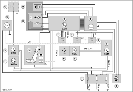
Index |
Explanation |
Index |
Explanation |
|---|---|---|---|
1 |
Centre console switch centre (SZM) |
2 |
Control electronics |
3 |
Left switch block |
4 |
Right switch block |
5 |
Body-gateway module (KGM) |
6 |
Roller sunblind motor |
7 |
Fuse carrier, rear |
8 |
Steering Column Switch Cluster (SZL) |
9 |
Switch for steering column adjustment |
10 |
Switch block seat adjustment, driver / passenger |
11 |
Seat Module, Driver |
12 |
Car Access System (CAS) |
13 |
Switch block, driver's door |
14 |
Roller sunblind button |
15 |
Steering column adjustment motor |
16 |
Steering column adjustment motor with Hall sensors |
17 |
Sport button |
|
|
The switch blocks are connected with the centre console switch cluster control module via the LIN bus. The status of the buttons is queried in cycles and transferred via the K-CAN to the body gateway module (KGM).
Depending on the equipment version, there are switch blocks with 1, 2 or 3 rows. In the versions with 1 and 2 rows, the function display is via LEDs in the buttons. In the 3-row version, the function display is via a pop-up menu in the Central Information Display (CID).
As a general principle, the button for the Dynamic Traction Control (DTC) or Park Distance Control (PDC) is located in the top row. If the vehicle does not have PDC, the button for the luggage compartment lid or roller cover is located here.
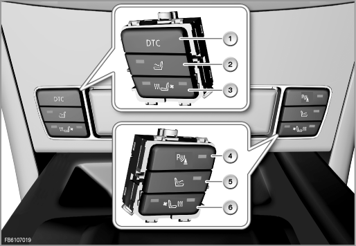
Index |
Explanation |
Index |
Explanation |
|---|---|---|---|
1 |
Dynamic Traction Control button |
2 |
Seat heating button, driver |
3 |
Active seat ventilation button, driver |
4 |
Park Distance Control button |
5 |
Seat heating button, passenger |
6 |
Active seat ventilation button, passenger |
The centre console switch cluster monitors the Hall sensors for the electrical steering column adjustment. This means that the Hall sensor impulses can be used as the basis for the position of the steering column for the steering column memory function.
The centre console switch cluster receives the request to activate the motors for steering column adjustment via the K-CAN. The control module forwards the request to the control electronics circuit, which activates the motors.
The button for the steering column adjustment evaluates the steering column switch cluster (SZL). The steering column switch cluster transmits the requests to the body gateway module (KGM) via the PT-CAN data bus. The KGM implements the signal on the K-CAN.
The request to actuate the roller sunblind is received via the K-CAN. The centre console switch cluster evaluates the request and the control electronics circuit activates the motor of the roller sunblind.
The button for the roller sunblind evaluates the switch block in the driver's door. The switch block in the driver's door is connected to the body gateway module (KGM) via a LIN bus. The KGM queries the status of the button from the switch block in the driver's door in cycles and implements the request to actuate the roller sunblind on the K-CAN.
Depending on the optional extras, pop-up menus can be displayed in the Central Information Display. The pop-up menus depend on the following additional seat functions:
Pressing the button of one of these seat functions switches on that function. When switching on, the highest level of the activated function is displayed first. Then, pressing the button again runs through the functions until the function is switched off or is reactivated.
The pop-up menus of the individual additional seat functions are as follows:
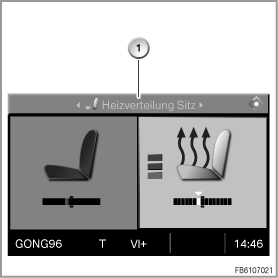
Index |
Explanation |
|---|---|
1 |
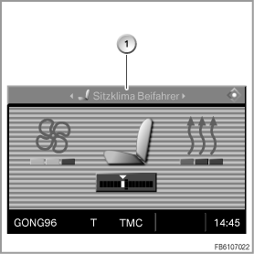
Seat heating |
The heat output is set using the button for the seat heating. The heat distribution is adjusted using the controller.
Index |
Explanation |
|---|---|
1 |
Active seat ventilation |
The settings for the air conditioning and heating function are made using the button in the switch block. The ratio of air conditioning to heating function is set using the controller.
Index |
Explanation |
|---|---|
1 |
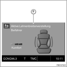
Backrest width adjustment |
The backrest width is set using the button in the switch block.
The SPORT button activates the Sport program (Dynamic Driving Control, FDC). The gearshift times are shortened. The shift characteristics are more sports-oriented. The engine is more responsive to movements of the accelerator pedal. Dynamic Driving Control is always deactivated when the engine is started.
In the versions of the button blocks with 1 and 2 rows, the function display is via LEDs in the buttons. In the version of the button blocks with 3 rows, only an 'on' indicator is possible via the LED. The function display is provided by a pop-up menu in the Central Information Display (CID).
The pop-up menu for the additional seat functions can be overridden by Check Control messages for the period in which Check Control messages are displayed. Running through the seat functions is still possible. The only display in this situation is the 'on' indicator via the LED of the button.
In vehicles without optional extra, the boot lid button is located on the A-pillar and redundantly in the centre console switch cluster.