Note! Optional extra 5DF depending on the country, only in conjunction with certain optional extras.
The active cruise control with Stop&Go function is currently only available with optional extra 205 ”Automatic transmission” or with optional extra 2TB ”Sports automatic transmission”.
In some markets, ACC is offered without the Stop&Go function due to official approval restrictions.
The only difference between this and ACC without the Stop&Go function is that there are no short-range sensors.
In Europe, optional extra 5DF is only offered in conjunction with the navigation system. Reason: legally prescribed shutdown when approaching radio-astronomy stations.
Index |
Explanation |
Index |
Explanation |
|---|---|---|---|
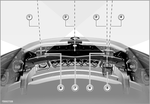
1 |
Centre axis of the short-range sensor, left |
2 |
Vehicle longitudinal axis |
3 |
Centre axis of the long-range sensor |
4 |
Centre axis of the short-range sensor, right |
5 |
Long-range sensor with bracket |
6 |
Short-range sensor, right, with bracket |
7 |
Bumper carrier |
8 |
Short-range sensor, left, with bracket |
Observe the following information in Service:
The following text describes the new active cruise control with Stop&Go function (optional extra 5DF).
Active cruise control with Stop&Go function is an extension of the familiar active cruise control (ACC).
As a supplement to the familiar active cruise control, the Stop&Go function enables:
The required speed can be selected in the range from 30 km/h to 180 km/h: in convenient steps of 10 or fine steps of 1. The required speed is displayed in the instrument cluster. Furthermore, it is also possible to choose between 4 distances.
With the new optional extra, a new sub-bus is also used: Sensor CAN (S-CAN).
The following components are described for ACC:
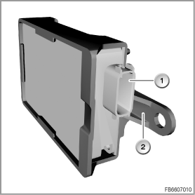
The short-range sensors are radar sensors (Short Range Radar).
For the ACC with Stop&Go function, 2 identical short-range sensors have been installed. The short-range sensors are mounted on the front bumper bracket with a bracket made of plastic.
Index |
Explanation |
Index |
Explanation |
|---|---|---|---|
1 |
Short-range sensor |
2 |
Bracket |
The short-range sensors are connected via the sensor CAN (S-CAN) with the LDM control module.
The short-range sensors have the following task:
The object data of the short-range sensors is only used for the ACC Stop&Go function (not for adaptive brake assist).
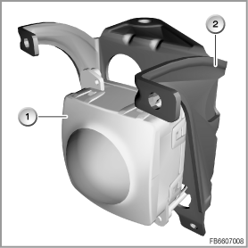
LRR stands for Long Range Radar.
Index |
Explanation |
Index |
Explanation |
|---|---|---|---|
1 |
long-range sensor |
2 |
Bracket |
The long-range sensor (former ACC sensor) is a radar sensor. At the same time, the long-range sensor is a control module. This means the long-range sensor has a control module address and can be diagnosed and programmed.
A long-range sensor senses the distance, angle as well as speed of moving objects. The area covered is up to 150 metres ahead of the vehicle. The data is processed in the LDM (longitudinal dynamics management) control module.
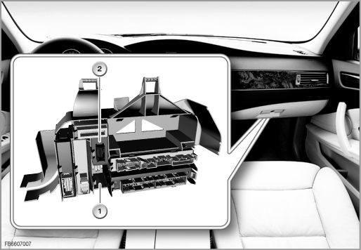
The control module for longitudinal dynamics management is installed on the carrier behind the glove compartment.
Index |
Explanation |
Index |
Explanation |
|---|---|---|---|
1 |
Device carrier |
2 |
LDM control module |
For ACC with Stop&Go function, the LDM control module performs the following tasks:
The LRR and LDM control module are supplied by the CAS control module with their own wake-up line that is electrically decoupled from the usual wake-up line. This solution was selected, as the long-range sensor is fitted in a zone that is subject to the risk of accident (vehicle front). If the wake-up line of the LRR were to be damaged in the event of an accident (e.g. short circuit to ground), this solution limits the effects on other control modules.
The new sensor CAN (S-CAN) connects:
The S-CAN was necessary due to the large data volume from the radar sensors.
This data volume would have exceeded the available transfer capacity on present bus systems.
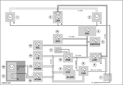
Index |
Explanation |
Index |
Explanation |
|---|---|---|---|
1 |
Short-range sensor, left |
2 |
Long-range sensor (LRR) |
3 |
Short-range sensor, right |
4 |
DSC (Dynamic Stability Control) |
5 |
DME (Digital Engine Electronics) or DDE (Digital Diesel Electronics) |
6 |
Longitudinal Dynamics Management (LDM) |
7 |
Fuse in the luggage compartment |
8 |
Car Access System (CAS) |
9 |
Car Communication Computer (CCC) and Multi-Audio System controller (M-ASK) |
10 |
Body-gateway module (KGM) |
11 |
Driver's door contact |
12 |
Electronic Transmission Control (EGS) |
13 |
Steering Column Switch Cluster (SZL) |
14 |
Light module (LM) |
15 |
Instrument cluster (KOMBI) |
16 |
Advanced Crash Safety Module (ACSM) |
17 |
Belt lock contact |
18 |
Seat occupation mat |
Characteristics of the sensor CAN:
The following system functions are described:
For implementation of the Stop&Go function, a complex composite system with distributed functions in other control modules is necessary. The LDM control module is connected across data bus with these other control modules.

Index |
Explanation |
Index |
Explanation |
|---|---|---|---|
1 |
Long-range sensor (LRR) |
2 |
Short-range sensor, left |
3 |
Short-range sensor, right |
4 |
Steering Column Switch Cluster (SZL) |
5 |
Body-gateway module (KGM) |
6 |
Instrument cluster (KOMBI) |
7 |
DSC (Dynamic Stability Control) |
8 |
Electronic Transmission Control (EGS) |
9 |
DME (Digital Engine Electronics) or DDE (Digital Diesel Electronics) |
10 |
Longitudinal Dynamics Management (LDM) |
The following control modules are networked for the overall function:
Control module |
Function |
|---|---|
DME or DDE: Motor control |
Implementation of the torque request ”Engine on” signal |
DSC: Dynamic Stability Control |
Driving situation Implementation of the brake intervention |
SZL: Steering column switch center |
Operating lever Steering angle Activation of fanfares |
CCC, M-ASK: Navigation system |
Data from navigation system (influence on control variables) |
KOMBI: Instrument cluster |
Diagram of the displays (ACC and Check Control messages) |
EGS: Transmission control |
Drive position |
CAS: Car Access System |
Terminal status and wake-up line |
KGM: Body Gateway Module |
Door contact (driver intends to exit) |
AHM: Trailer Module |
Detection of trailer towing |
ACSM. Crash Safety Module |
Driver's seat occupation (driver intends to exit) Belt lock contact (driver intends to exit) |
RLS: Rain / driving light sensor |
Road surface condition (wet) |
SZM: Center Console Switch Center |
DTC button |
LM: Light module |
Activation of hazard warning system |
The adaptive brake assist is a function of the DSC. The LDM control module is the gateway from the S-CAN to the PT-CAN.
The adaptive brake assist provides its greatest benefit in emergency braking situations. If the driver of the vehicle ahead brakes suddenly, the long-range sensor detects this situation.
The brake assist supports the driver in optimising the brake operation, preventing a run-up collision in the best case.
The following functions are available:
The adaptive brake assist is always switched on when the ACC is active.
The adaptive brake assist is also function in the case of ACC without Stop&Go function.
A situation that requires explaining to the driver may occur if the function limits of the ACC system are reached. Such situations are described in the following:
No liability can be accepted for printing or other faults. Subject to changes of a technical nature