The FKA is offered as an optional extra for the IHKA. The FKA regulates the rear air conditioning/heating.
The following components are described for the rear heater / air-conditioning system, FKA:
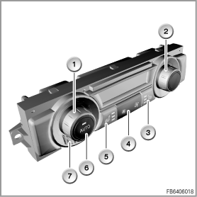
The control module for the rear heater / air-conditioning system FKA is fitted in the centre between the front seats. The FKA is operated using the operating elements shown in graphic 1. The control module picks up the sensor signals. On the basis of the signals and the set nominal temperature, the control module regulates the rear air conditioning/heating. Moreover, the seat heating systems (if fitted) are operated via buttons in the operating unit.
Index |
Explanation |
Index |
Explanation |
|---|---|---|---|
1 |
Temperature dial, rear left |
2 |
Temperature dial, rear right |
3 |
Seat heating switch, rear right |
4 |
Blower buttons |
5 |
Seat heating switch, rear left |
6 |
AUTO button |
7 |
Air inlet grill of the internal temperature sensor |
|
|
The following sensors are fitted in the rear heater / air-conditioning system to measure the rear compartment temperatures:
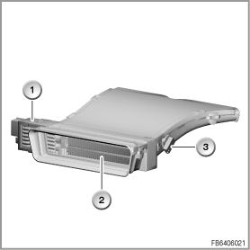
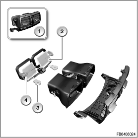
The electrical auxiliary heater based on the PTC principle (positive temperature coefficient) is fitted in the heater/air conditioner. The electrical auxiliary heater directly heats up the air to adjust the temperature of the vehicle interior. Electrical auxiliary heaters are fitted on the right and left. The heating elements in the electrical auxiliary heater are cold conductors. These heating elements consist of individual ceramic semiconductor resistors.
Index |
Explanation |
Index |
Explanation |
|---|---|---|---|
1 |
Plug-in connection |
2 |
Heating elements of the electrical auxiliary heater |
3 |
Footwell temperature sensor |
|
|
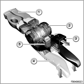
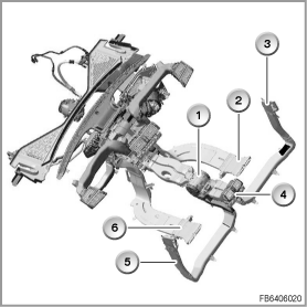
The blower creates the necessary air-mass flow. The blower is built into the heater/air conditioner. The blower output stage is mounted directly at the housing of the blower motor. The blower output stage is activated by the FKA control module with a pulse-width modulated signal.
Index |
Explanation |
Index |
Explanation |
|---|---|---|---|
1 |
Air duct, centre console |
2 |
Rear compartment blower |
3 |
Duct to the ventilation grille, rear centre |
4 |
Air duct, B-pillars |
5 |
Blower output stage of the FKA |
|
|
The following system functions are described for the FKA rear heater / air-conditioning system:
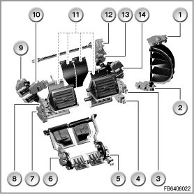
The air distribution is controlled automatically by the FKA control module. Here, it is important that all the air vents are opened. A manual setting at the operating unit is not possible. The following graphic provides an overview of the air distribution flap for the IHKA HIGH with 4 zones and rear air conditioning.
Index |
Explanation |
Index |
Explanation |
|---|---|---|---|
1 |
Fresh air circulating-air-flap motor |
2 |
Shut-off flap for ventilation, rear centre FKA |
3 |
Ventilation actuator motor, front right |
4 |
Stratification actuator motor, front right |
5 |
Stratification / shut-off actuator motor, rear right |
6 |
Stratification actuator motor, rear left/right |
7 |
Stratification actuator motor, front left/right |
8 |
Ventilation actuator motor, front left/right |
9 |
Actuator motor in footwell, front left |
10 |
Actuator motor in footwell, rear left |
11 |
Housing for internal non-return flaps |
12 |
Defrost actuator motor |
13 |
Actuator motor in footwell, front left/right |
14 |
Actuator motor in footwell, rear right |
The rear centre air vent is shown in the following illustration.
Index |
Explanation |
Index |
Explanation |
|---|---|---|---|
1 |
Ventilation grille, rear centre FKA |
2 |
Shut-off flap for ventilation, rear centre FKA |
3 |
Stratification control wheel, rear |
4 |
Ventilation temperature sensors |
The blower speed can be set using 2 buttons on the operating unit. The set blower speed is shown in the display in a bar gauge. In the automatic mode, the blower speed is set by the control module.
An overview of the FKA is provided in the following graphic.
Index |
Explanation |
Index |
Explanation |
|---|---|---|---|
1 |
Rear compartment fan with blower output stage |
2 |
Electrical auxiliary heater, rear right |
3 |
Rear ventilation air vents, right |
4 |
Rear centre vent |
5 |
Rear ventilation air vents, left |
6 |
Electrical auxiliary heater, rear left |
The nominal temperature is set individually for the right-hand and left-hand side using the temperature selection dials. The set nominal temperatures are shown in the display. Depending on the set nominal temperature as well as the measured sensor temperatures, the temperature mixing flaps are adjusted. If required, the electrical auxiliary heater is also switched on.
The temperature is regulated using a master controller. The control operation is based on the set nominal value and the calculated actual value. The actual value is determined from measured values of the internal temperature sensor, the ventilation temperature sensor as well as the footwell temperature sensor. The setpoint value is corrected in the control module as a function of the outside temperature. In this way, e.g. when it is cold, the nominal value is raised in order achieve a pleasant climate despite the nominal value not having been adjusted.
The seat heating is offered as an optional extra. The seat heating is switched on and off using 2 buttons on the FKA operating unit. Seat heating is fitted on the right-hand and left-hand seats. The seat heating is switched in 3 stages. The status is indicated via function LEDs in the buttons.
The AUTO function is activated by pressing the AUTO button in the left-hand temperature dial. When the AUTO function is activated, the function LED in the button lights up green. Depending on the set nominal temperatures, the control module automatically regulates the rear air conditioning/heating. If required, the electrical auxiliary heaters are switched on. The blower speed is set automatically.
The flap motors are processed within the framework of diagnosis of the IHKA. More detailed information on this can be found in the functional description for the IHKA.
For diagnosis of the electrical auxiliary heater, refer to the individual functional descriptions of the electrical auxiliary heaters.
No liability can be accepted for printing or other faults. Subject to changes of a technical nature