For certain known fault profiles, design measures have already been implemented in production.
Check these design measures in the event of EMC faults:
Index |
Explanation |
Index |
Explanation |
|---|---|---|---|
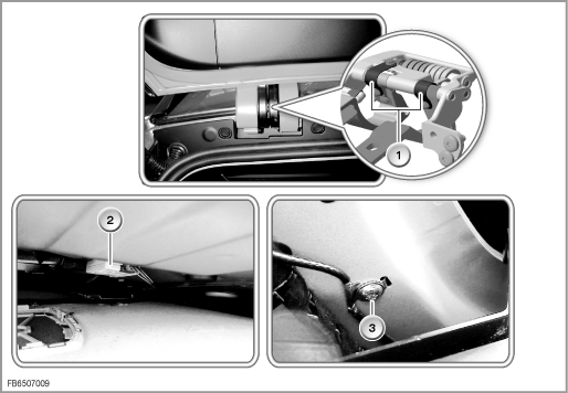
1 |
Earth strap on the luggage compartment lid: |
2 |
Suppressor filter for the additional brake light: |
3 |
Cable choke: |
|
|
Index |
Explanation |
Index |
Explanation |
|---|---|---|---|
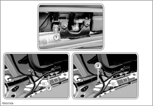
1 |
Earth strap on the luggage compartment lid: |
2 |
Suppressor filter for the additional brake light: |
3 |
Cable choke: |
|
|
The antenna diagnosis runs as follows:
The self-diagnosis of the antenna diversity is triggered in the test module of the BMW diagnosis system. The self-diagnosis includes a check of the antenna inputs on the basis of a current measurement (direct current). If a fault is found, the antenna diagnosis aborts after the self-diagnosis.
If the self-diagnosis has a positive result, the FM antennas are specifically activated and evaluated with regard to field strength (check of the antennas).
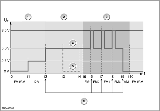
Diagram of antenna diagnosis:
Index |
Explanation |
Index |
Explanation |
|---|---|---|---|
1 |
Normal receive mode (t1 to t2: diversity 2.5 Volt) |
2 |
Self-diagnosis |
3 |
Test of the antennas (t6 to t8: switching pulse 8.5 Volt) |
4 |
Self-diagnosis has positive result (t2 to t5: 5 Volt) |
5 |
Self-diagnosis has negative result: Fault detected (t3 to t4: 0 Volt) |
6 |
Actions triggered by the antenna diagnosis (t9: AM 0 Volt |
No liability can be accepted for printing or other faults. Subject to changes of a technical nature